RTC
®
5 PC Interface Board
Rev. 1.9 e
16 Appendix B: The RTC
®
5-Express Board
593
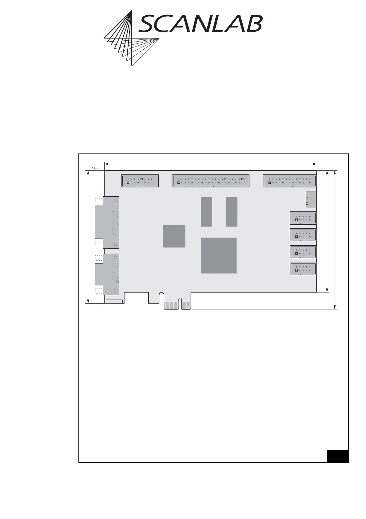
16.2 Layout and Interfaces
16.2.1 Connectors and Jumper Posi-
tions
Figure 68 and figure 69 on page 594 show the posi-
tions of the connectors and jumpers on the front and
back side of the RTC
®
5-Express board.
Relating the connectors and jumper settings, the
RTC
®
5-Express board differs from the
RTC
®
5 PC interface board only in its interface to the
PC and in its configuration of the “SPI / I2C”
connector. These two deviations from the
RTC
®
5 PC interface board are described in the
following sections.
Legend
SCAN HEAD . . . . . . . . . . . . Primary scan head connector (D-SUB 9-pin female, pin-out see page 41)
LASER . . . . . . . . . . . . . . . . Laser connector and digital and analog output ports (D-SUB 15-pin female,
pin-out see page 46)
MARKING ON THE FLY . . . . 16-pin socket connector with encoder inputs, (optionally) for Processing-on-
the-fly applications (pin-out see page 51)
EXTENSION 1 . . . . . . . . . . . 40-pin socket connector with a 16-bit digital input and a 16-bit digital output
(pin-out see page 49)
EXTENSION 2 . . . . . . . . . . . 26-pin socket connector with an 8-bit digital output port, e.g. for alternative
laser control (pin-out see page 50)
SLAVE . . . . . . . . . . . . . . . . 6-pin SLAVE connector (see "Master/Slave Synchronization", page 40)
2. SCAN HEAD . . . . . . . . . . 10-pin socket connector for secondary scan head control (optionally acti-
vated, pin-out see page 41)
STEPPER MOTOR . . . . . . . . 10-pin socket connector for stepper motor control (pin-out see page 53)
RS232 . . . . . . . . . . . . . . . . 10-pin socket connector for controlling external devices via RS232 interface
(pin-out see page 51)
SPI / I2C . . . . . . . . . . . . . . . 10-pin socket connector (serial extension interface, pin-out see page 595)
ID. . . . . . . . . . . . . . . . . . . . ID number
PCIe-x1Connector . . . . . . . Interface to PC (see page 594)
68
9
6
51
J11
1
J10
15
8
9
115
216
J6
1
2
39
40
J5 J4
2
25
26
1
J3
1
J7
102
9
1
J12
102
9
1
J9
102
9
1
J8
102
9
1
2. SCAN HEAD
STEPPER MOTOR
RS232
SPI / I2C
LASER
SCANHEAD
MARKING ON THE FLY
EXTENSION 1
EXTENSION 2
SLAVE
104.5 mm
160 mm
ID
91.75 mm
100 mm
PCIe-x1 Connector
Layout of the RTC
®
5-Express board (front side)