RTC
®
5 PC Interface Board
Rev. 1.9 e
7 Basic Functions for Scan Head and Laser Control
118
after deactivation of Sky Writing mode. Deacti-
vation of Sky Writing mode results in some
circumstances in addition of a mark delay defined
prior to activation (see page 116).
• In Sky Writing mode 1, the run-in and run-out
phases take place fully within the respective
marking command. As a result, execution of the
marking command is extended by a time period
(in 10 µs) of (2 ·
Nprev
+ 2 ·
Npost
). In Sky Writing
mode 2 and 3 execution is extended by a time
period (in 10 µs) of at least (
Nprev
+
Npost
).
• In Sky Writing mode 1, jump delays are
performed normally. The jump delay value (in
10 µs, see set_scanner_delays) can be reduced
by approx. (2 ·
Nprev
) or even to 0. In Sky Writing
mode 2 and 3, the jump delay is automatically
(internally, dynamically) reduced by up to
Nprev
.
• Time-based mark and arc commands can also be
performed in Sky Writing mode (see page 198).
Here, however, a shorter marking period is
coupled with a higher marking speed and
therefore with longer starting and ending
distances and acceleration phase in the run-in
and run-out phases. Herefore,
Nprev
and
Npost
can be separately adjusted with respect to the
specified marking duration (with
set_sky_writing the
Timelag
parameter might
have to be adjusted with respect to the specified
marking duration).
• During execution of para commands (e.g. with
activated vector-defined laser control, see
page 147) and during execution of micro vector
commands (see page 197), the Sky Writing mode
is not taken into account (but also not deacti-
vated).
• With Sky Writing mode 2 or 3 activated, the two
following RTC
®
5 functionalities of the 2D jump
commands jump_abs and jump_rel get deacti-
vated:
– Tuning auto-switching in jump mode (see
page 156)
– Coordinate transformations with
at_once
= 2
(see page 163)
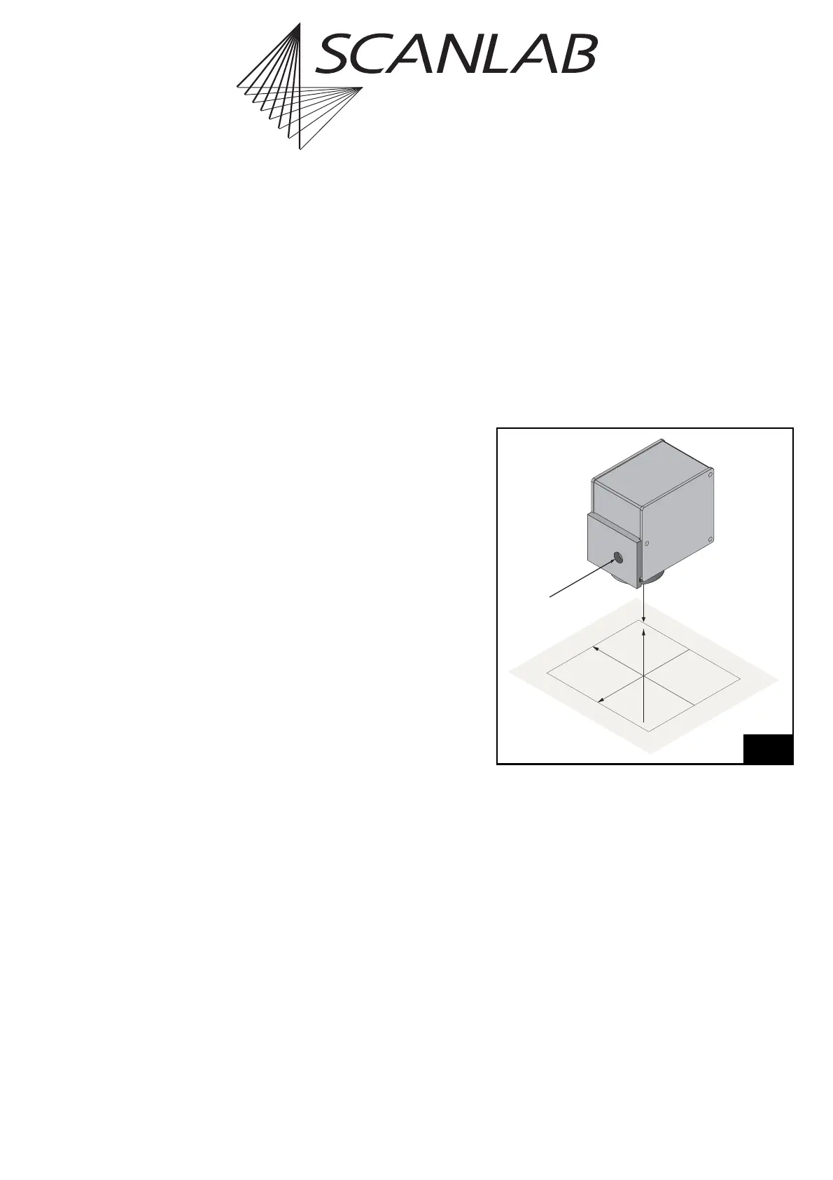
7.3 Scan Head Control
7.3.1 Reference System
Figure 44 shows the reference system for the image
field which is used by the RTC
®
5. The Y-axis points
in the reverse direction of the input laser beam, the
Z-axis points in the reverse direction of the output
laser beam. X-axis, Y-axis and Z-axis form a right-
handed reference system. The origin of the reference
system, i.e. the point (0|0|0), is in the center of the
image field.
input
laser beam
beam out
(0|0|0)
X
Y
Z
Reference system for the RTC
®
5 coordinates