detail in the following sections.
71
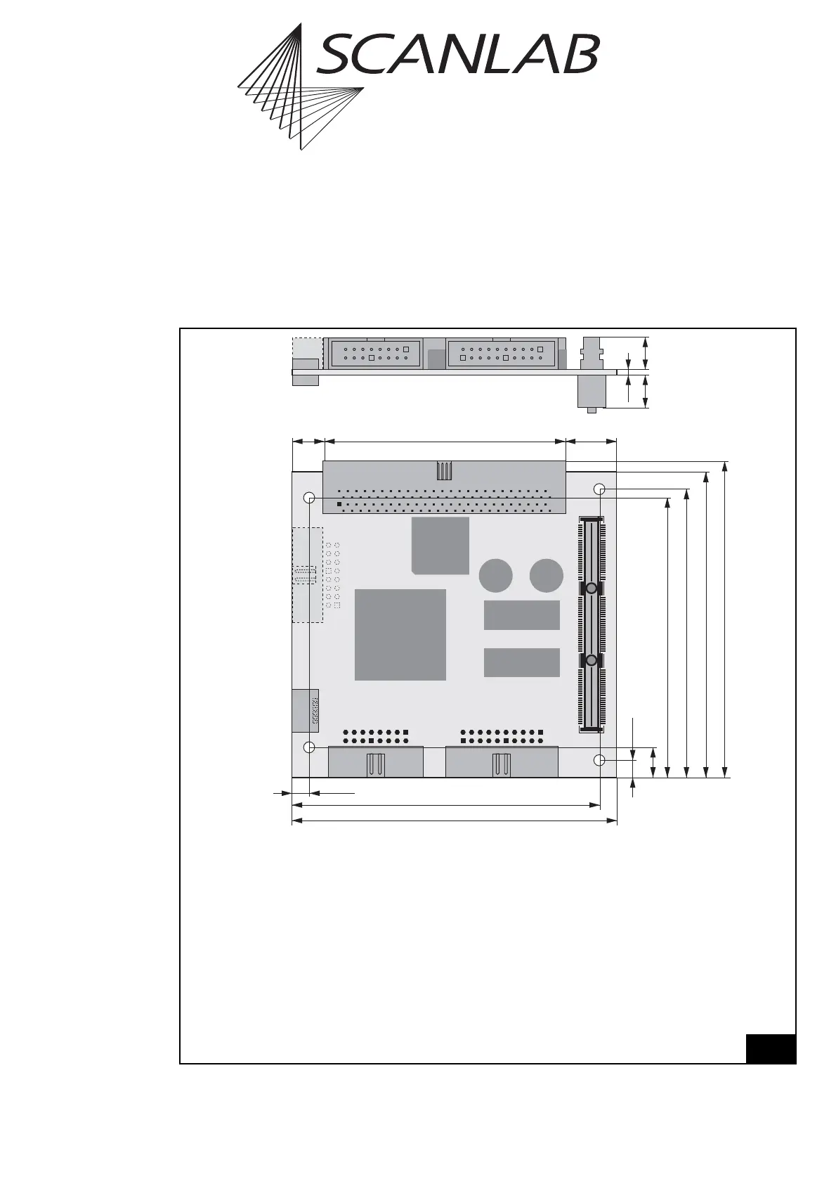
Legend
SCANHEADS . . . . . . . . . . . Primary and secondary scan head connection (20-pin box header, double-row,
2.54 mm pitch, pin-out page 579); secondary scan head control is only
optionally activated.
LASER . . . . . . . . . . . . . . . . Laser connection and digital and analog output ports (16-pin box header,
double-row, 2.54 mm pitch, pin-out page 580)
MULTI . . . . . . . . . . . . . . . . Multifunction connector with a 16-bit digital input, a 16-bit digital output, an
8-bit digital output, encoder inputs for Processing-on-the-fly applications, etc.
(100-pin box header, double-row, 1.27 mm pitch, pin-out page 580)
PCI-Express . . . . . . . . . . . . PCI-Express- (156-pin, see page 579)
SLAVE . . . . . . . . . . . . . . . . 6-pin SLAVE connector (see "Master/Slave Synchronization", page 579)
MARKING ON THE FLY . . . . optional 16-pin box header (double-row, 2.54 mm pitch) with encoder inputs
for Processing-on-the-fly applications (pin-out page 51)
Layout and dimensions of the RTC
®
5 PCIe/104 board (top: side view, bottom: front side)