RTC
®
5 PC Interface Board
Rev. 1.9 e
4 Layout and Interfaces
54
For programming the stepper motor signals, see
chapter 9.1.5 "Stepper Motor Control", page 205.
4.4.8 Analog Inputs
When the RTC
®
5 PC interface board is equipped with
the RTC
®
5 ADC add-on board (product number
121126), two 10 V analog inputs become available
(ANALOG IN0 and ANALOG IN1).
The analog input values of the two inputs are auto-
matically (without any command call) converted in an
endless series (duration approx. 0.3 ms) and trans-
ferred to the DSP as 12-bit digital values (I²C bus with
400 kHz, fast mode).
The current input values can be read via the control
command read_analog_in at any time (see below).
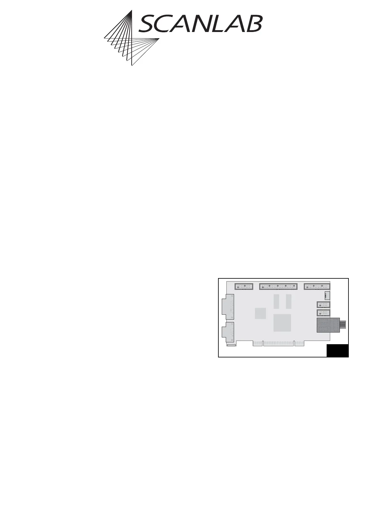
Installation and Pinout
The ADC add-on board must be plugged into the
RTC
®
5 board’s “SPI / I2C” and “RS232” headers.
When installing, ensure that the add-on board is
correctly oriented (see figure 24): the soldered-on flat
ribbon cable must point outward.
Internally, the ADC add-on board is only electrically
connected to pins 1, 2, 9 and 10 of the “SPI / I2C”
header. Attachment to the “RS232” header is only for
mechanical stability.
2. SCAN HEAD
STEPPER MOTOR
RS232
SPI / I2C
LASER
SCANHEAD
MARKING ON THE FLY
EXTENSION 1
EXTENSION 2
SLAVE
ID
RS232
RTC
®
5 with ADC add-on board