RTC
®
5 PC Interface Board
Rev. 1.9 e
4 Layout and Interfaces
55
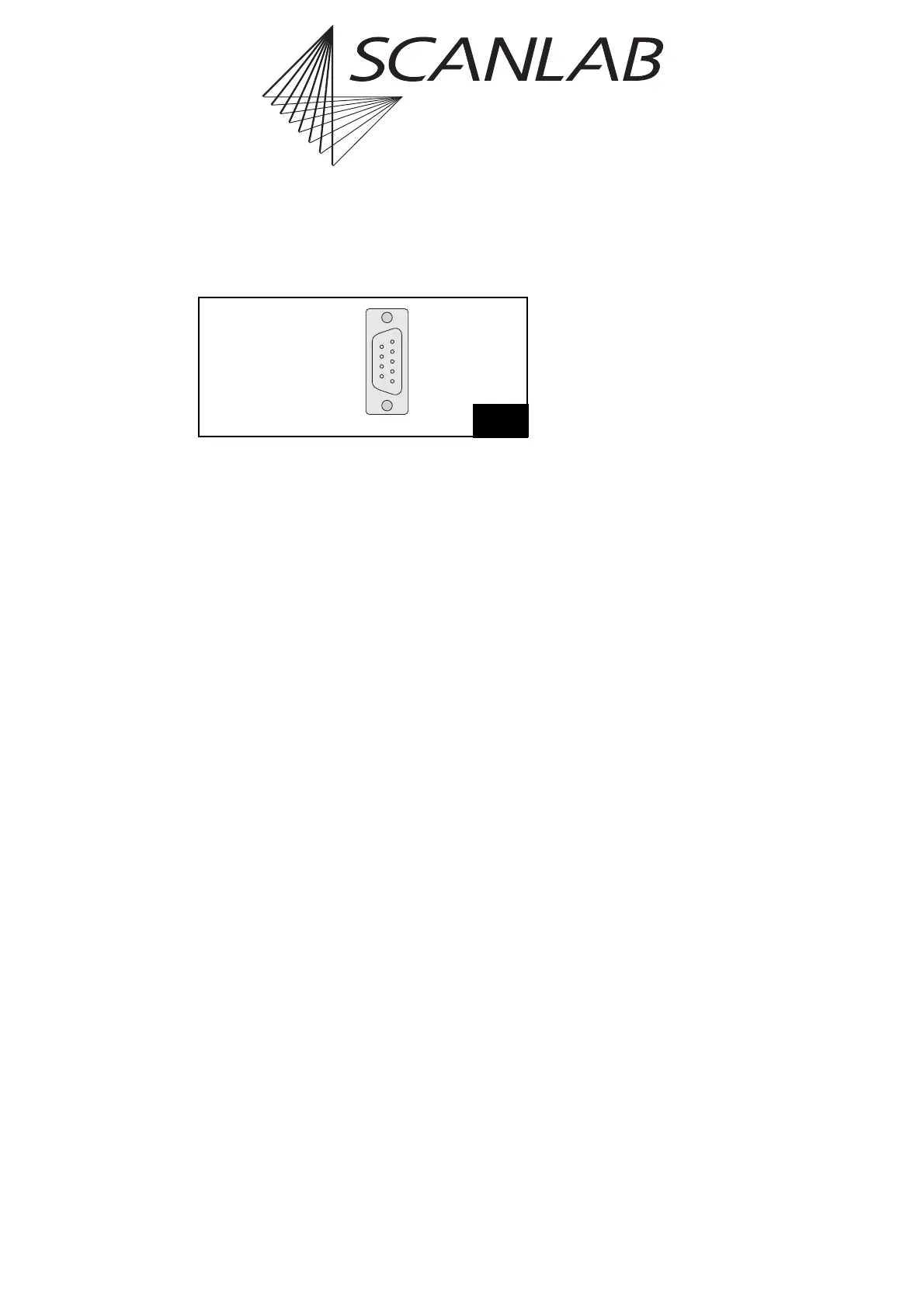
The analog inputs are then available via a 9-pin D-SUB
connector at the soldered-on flat ribbon cable. Its
pinout is shown in figure 25.
Specifications
• Input voltage range: 0 V … 10 V
• Input resistance: 4 k
• ADC resolution: 12 bit
The input signals are referenced to PC ground GND.
Note
• Actually, the ADC add-on board even provides a
third 10 V analog input ANALOG IN2 with
identical specifications (also see figure 25); but
input values of this third analog input is not
queryable via read_analog_in.
25
(1) GND
(2) GND
(3) GND
(4) GND
(5) GND
ANALOG IN0 (6)
ANALOG IN1 (7)
ANALOG IN2 (8)
DO NOT CONNECT (9)
Pinout of the ADC add-on board’s 9-pin D-SUB connector