RTC
®
5 PC Interface Board
Rev. 1.9 e
4 Layout and Interfaces
46
4.4 Interfaces for the Laser and
Peripheral Equipment
4.4.1 Laser Connector
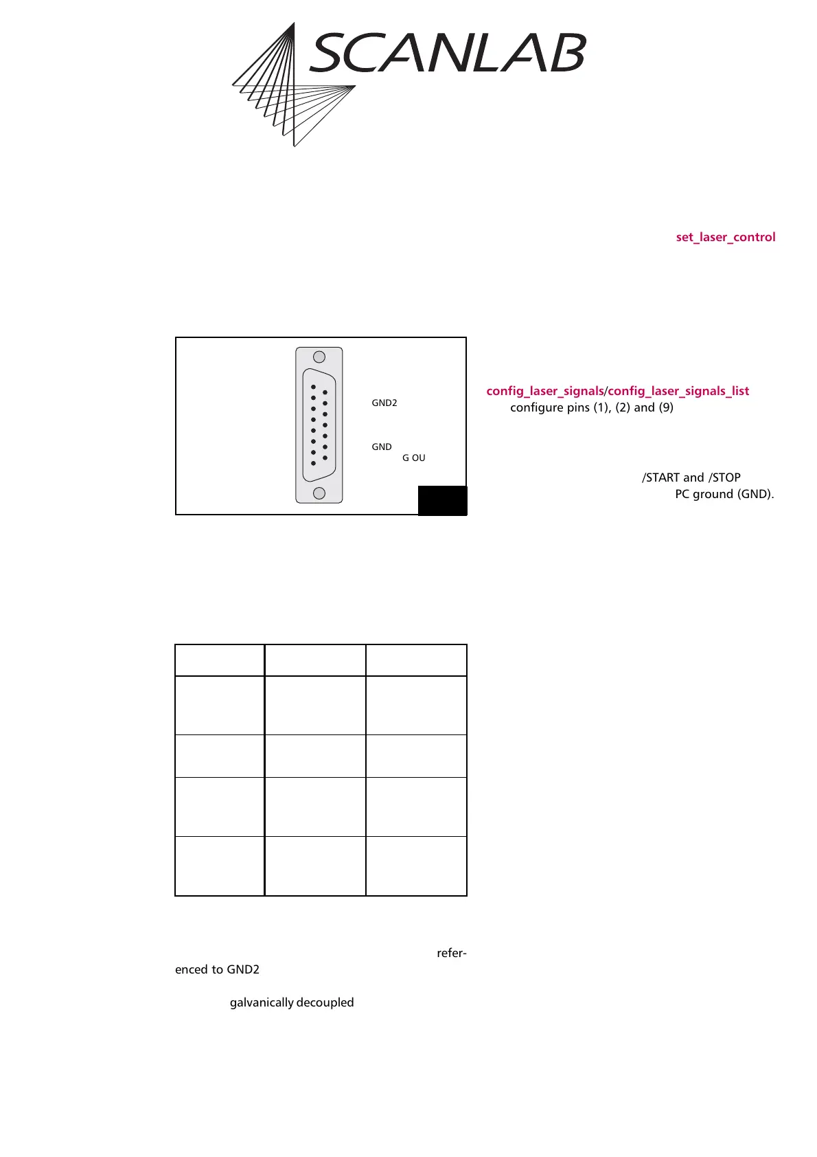
Figure 10 shows the pin-out of the 15-pin D-SUB
connector for the laser.
Laser Signals
The output signals LASER1 and LASER2 depend on
the selected laser control mode (see "Laser Control",
page 128):
All laser output signals (LASERON, LASER1 and
LASER2) are continuously generated by the RTC
®
5
board. They are digital TTL level signals and are refer-
enced to GND2. If the RTC
®
5 is supplied with opto-
electronic couplers, then GND2 and the laser output
signal are galvanically decoupled from the PC ground
(GND). Otherwise, GND and GND2 are identical. See
chapter 2.3 "Optional Functionality", page 27.
The maximum current load is 20 mA.
All laser signals can be set to either active-low or
active-high logic via the command set_laser_control
(see page 440). Active-low means that a logical 1
(“Laser On“, for instance) is represented by a LOW
level (0 V, TTL). Active-high means a logical 1 is repre-
sented by a HIGH level (+5 V, TTL). Set the TTL laser
signal level according to the specifications of your
laser control. Refer to the documentation of your
laser.
The commands
config_laser_signals/config_laser_signals_list let
you configure pins (1), (2) and (9) of the laser
connector (see page 130).
External Control Signals
The external control signals /START and /STOP
(TTL active-low) are referenced to PC ground (GND).
Both input signals are connected internally to +3.3 V
via pull-up resistors. Refer to the section "Starting and
Stopping Lists via External Control Signals and
Master/Slave Synchronization", page 209.
BUSY Status
The BUSY status is available as the BUSY OUT signal
at pin (4). The BUSY OUT signal is HIGH when the
BUSY status is set (see "List Execution Status", page
73). The signal is referenced to GND.
Digital Input and Output
The RTC
®
5 provides a 2-bit digital input (DIGITAL IN1
and DIGITAL IN2) and a buffered 2-bit digital output
(DIGITAL OUT1 and DIGITAL OUT2).
For programming the input and output see "2-Bit
Digital Input", page 207 and "2 Bit Digital Output
Port", page 204.
Input signals:
• LOW level< 0.6 V, HIGH level > 2.3 V
• Max. input voltage range: –0.5 V … +5.5 V
• Input impedance (pull-up) > 4.7 k
Output signals:
• LOW level < 0.55 V, HIGH level > 3.8 V,
• Maximum signal current load 20 mA
The signals are referenced to GND.
LASER1 LASER2
CO
2
mode Modulation
pulse 1 or
standby signal
Modulation
pulse 2 or
standby signal
YAG modes
1-3, 5
Q-Switch signal FirstPulseKiller
signal
Laser mode 4 Modulation
pulse or
standby signal
FirstPulseKiller
signal
Laser mode 6 Modulation
pulse or
standby signal
–
10
(9) LASER2
(10) GND2
(11) /STOP
(12) DIGITAL OUT1
(13) DIGITAL IN1
(14) GND
(15) ANALOG OUT2
LASER1 (1)
LASERON (2)
/START (3)
BUSY OUT (4)
DIGITAL OUT2 (5)
DIGITAL IN2 (6)
+5 V (7)
ANALOG OUT1 (8)
Pin-out of the 15-pin female D-SUB connector for the laser (LASER)