EasyManua.ls Logo

Scanlab RTC 5 PC Interface Board - Page 45

Scanlab RTC 5 PC Interface Board
622 pages
Print Icon
To Next Page IconTo Next Page
To Previous Page IconTo Previous Page
Loading...
RTC
®
5 PC Interface Board
Rev. 1.9 e
4 Layout and Interfaces
45
innovators for industry
9
1
6
2
7
3
8
4
9
5
1
6
2
7
3
8
4
9
5
DATA IN+
DATA IN
DATA OUT
DATA OUT+
DATA IN+
DATA IN
DATA OUT
DATA OUT+
Shielding
D-SUB
9 pin male
D-SUB
9 pin male
Scan head
Control
1
14
2
15
3
16
4
17
5
18
6
19
7
20
8
21
9
22
10
23
11
24
12
25
13
1
14
2
15
3
16
4
17
5
18
6
19
7
20
8
21
9
22
10
23
11
24
12
25
13
CLOCK
CLOCK+
SYNC
SYNC+
CHAN1
CHAN1+
CHAN2
CHAN2+
STATUS *
STATUS+ *
STATUS1 *
STATUS1+ *
CLOCK
CLOCK+
SYNC
SYNC+
CHAN1
CHAN1+
CHAN2
CHAN2+
STATUS *
STATUS+ *
STATUS1 *
STATUS1+ *
D-SUB
25 pin male
D-SUB
25 pin male
Shielding
Ferrit ring
Scan head
Control
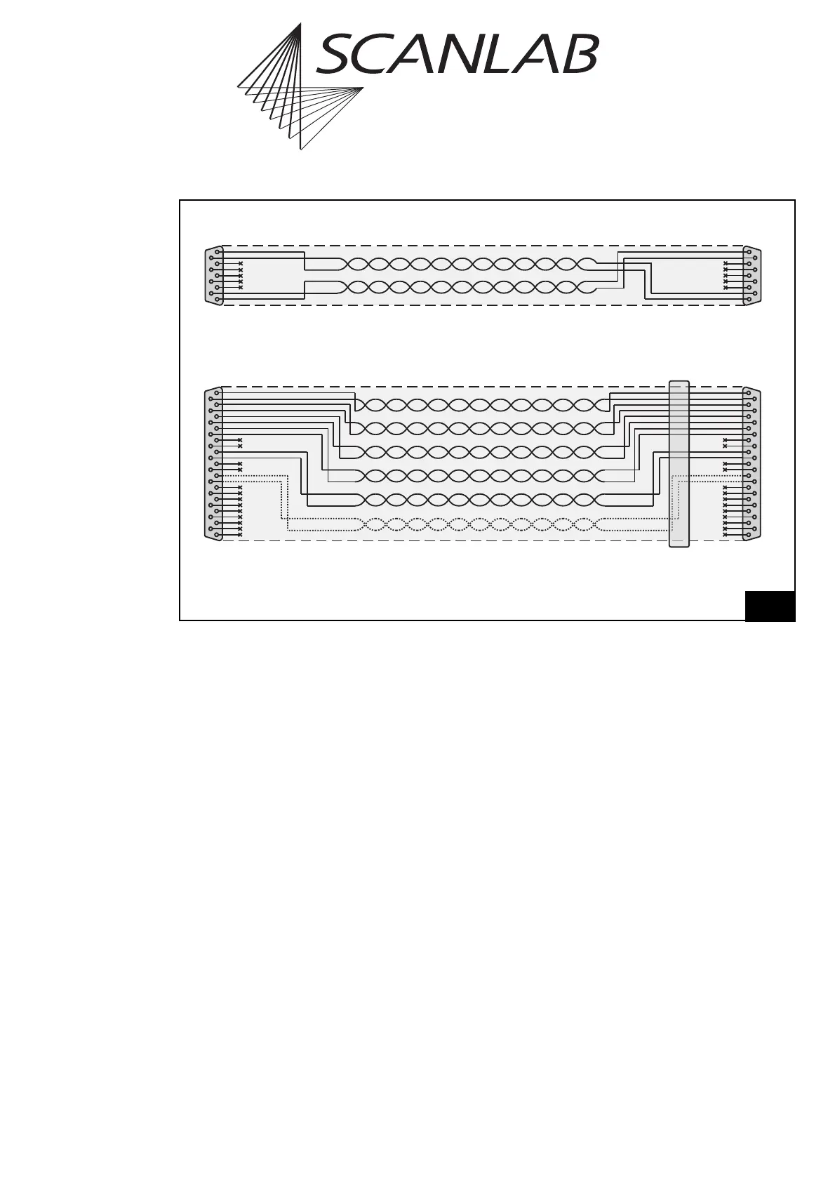
SL2-100-compliant data transmission
XY2-100-compliant data transmission
* For iDRIVE
®
scan systems (intelliSCAN
®
, intelliSCAN
de
®
, intelliDRILL
®
, intellicube
®
, intelliWELD
®
, varioSCAN
de
), the
STATUS± channel is the status channel of axis 2 (X axis; this channel is then also called STATUS2±) and the STATUS1±
channel is the status channel of axis 1 (Y axis). For other scan systems, the STATUS1± channel is not needed.
Data cable layout and pin assignments

Table of Contents

Related product manuals