RTC
®
5 PC Interface Board
Rev. 1.9 e
4 Layout and Interfaces
40
4.2 Interface to PC
The RTC
®
5’s PCI connector is the interface to the PC.
The RTC
®
5 can be installed into any IBM-compatible
personal computer with a PCI bus interface and at
least one free PCI slot.
4.2.1 Master/Slave Synchronization
If multiple synchronously-clocked RTC
®
5 boards are
to be used in a PC, then the RTC
®
5 boards must first
be connected pairwise with each other via the
MASTER and SLAVE connectors and then installed in
adjacent PCI slots. Always connect a board’s MASTER
connector to the SLAVE connector of another board.
Suitable connection cables are available from
SCANLAB.
Also see chapter 6.6.3 "Master/Slave Operation",
page 84 and "Starting and Stopping Lists via External
Control Signals and Master/Slave Synchronization",
page 209.
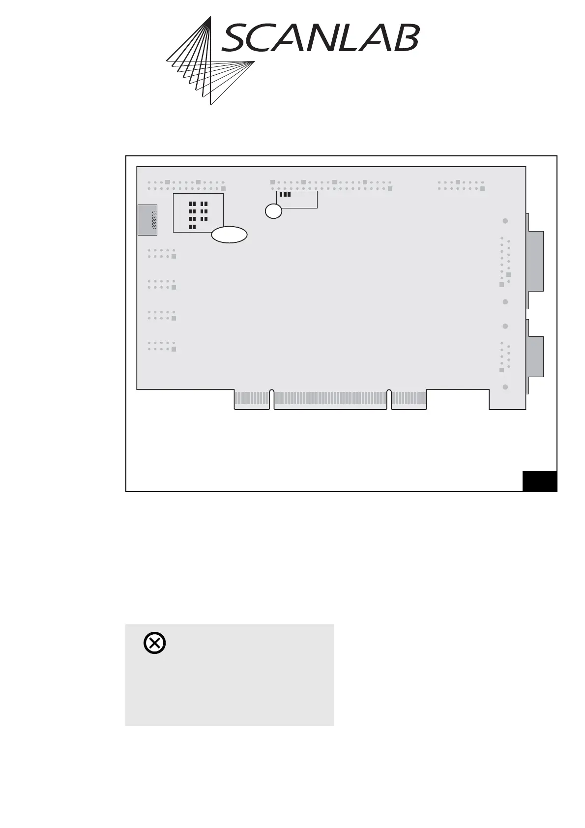
Legend
Master . . . . .6-pin MASTER connector (see "Master/Slave Synchronization", page 40)
JP1 . . . . . . . . Jumper for selecting the output signal level at the EXTENSION 1 connector
(see page 49)
JP2 - JP8 . . . . Jumpers for configuring the EXTENSION 2 connector signals (see page 50)
3
1
J2
1
Master
Digital I/O
Voltage
5V
3.3V
Pin17 Pin15
Data7
Data7
+5V
+5V
GND
GND
Latch
JP2 - JP8
JP1
Layout of the RTC
®
5 (back side)
Caution!
•The RTC
®
5 board does not support power-
saving modes that switch off power to the PCI
bus. Accordingly, you must disable standby or
sleep modes of the operating system. Also see
the note on page 27.