RTC
®
5 PC Interface Board
Rev. 1.9 e
16 Appendix B: The RTC
®
5-Express Board
595
16.2.3 McBSP Interface and Analog
Inputs
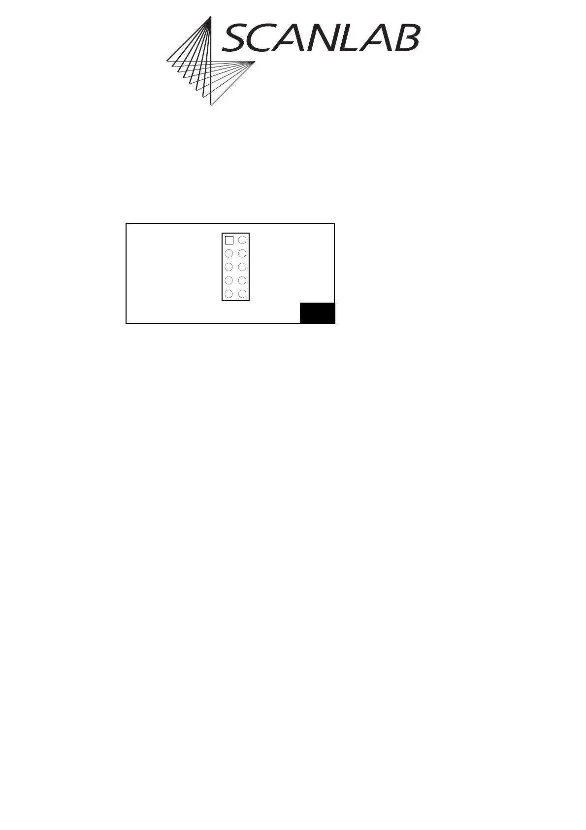
The “SPI / I2C” connector provides an McBSP
interface (Multi channel Buffered Serial Port) and two
analog inputs. The pin-out is shown in figure 70.
McBSP Interface
The McBSP interface and the corresponding
commands are identical to that of the
RTC
®
5 PC interface board (see page 52).
Analog Inputs
The RTC
®
5-Express board provides two 10 V analog
inputs (ANALOG IN0 and ANALOG IN1) at the
“SPI / I2C” connector (instead of the I
2
C interface
which is provided by the RTC
®
5 PC interface board;
similar to the RTC
®
5 PC interface board’s optional
ADC add-on board).
For using these analog inputs and for their
specifications refer to chapter 4.4.8, page 54.
70
Analog IN0 (1)
CLKX0 (3)
FSX0 (5)
DX0 (7)
GND (9)
(2) Analog IN1
(4) CLKR0
(6) FSR0
(8) DR0
(10) 3.3 V
Pin-out of the (on-board) “SPI / I2C” connector