RTC
®
5 PC Interface Board
Rev. 1.9 e
4 Layout and Interfaces
52
4.4.6 McBSP and I
2
C Interface
The “SPI / I2C” connector provides an McBSP
interface (Multi channel Buffered Serial Port) and an
I
2
C interface. The pin-out is shown in figure 21.
I
2
C Interface
The signals of the I
2
C interface (SCL, SDA) are not yet
available.
McBSP Interface
The McBSP interface and its associated commands
are primarily available for directly integrating
position signals into applications.
• In Processing-on-the-fly applications, for
example, a robot arm’s position signals can be
used to implement laser material processing via
moving scan systems (see page 177 and
page 216) – as an alternative to encoder-control
based Processing-on-the-fly processing of
moving workpieces.
• Another possibility is to use the McBSP interface’s
received position signals to align the scan system
above the workpiece with controllable timing
(see "Online Positioning", page 165 and
page 216).
The signal input and output ports of the McBSP
interface can also be used for other purposes. For
programming signal output and input via the McBSP
interface, see page 207 and page 216.
Data transfer is via the SPI interface, but the McBSP
protocol is used instead of the so-called SPI protocol.
The mcbsp_init command allows setting
DataDelay N independently for the transmitter and
receiver. Possible values range from 0 to 2 (default: 1).
All signals are referenced to PC ground GND.
RTC
®
5 as transmitter
The following specifications apply to transmitter
signals of the McBSP interface (CLKX0, FSX0, DX0):
• Signal level 3.3 V TTL
• McBSP mode:
– Single phase frame
– Single element per frame
– 32 bits per element
– DataDelay N bit
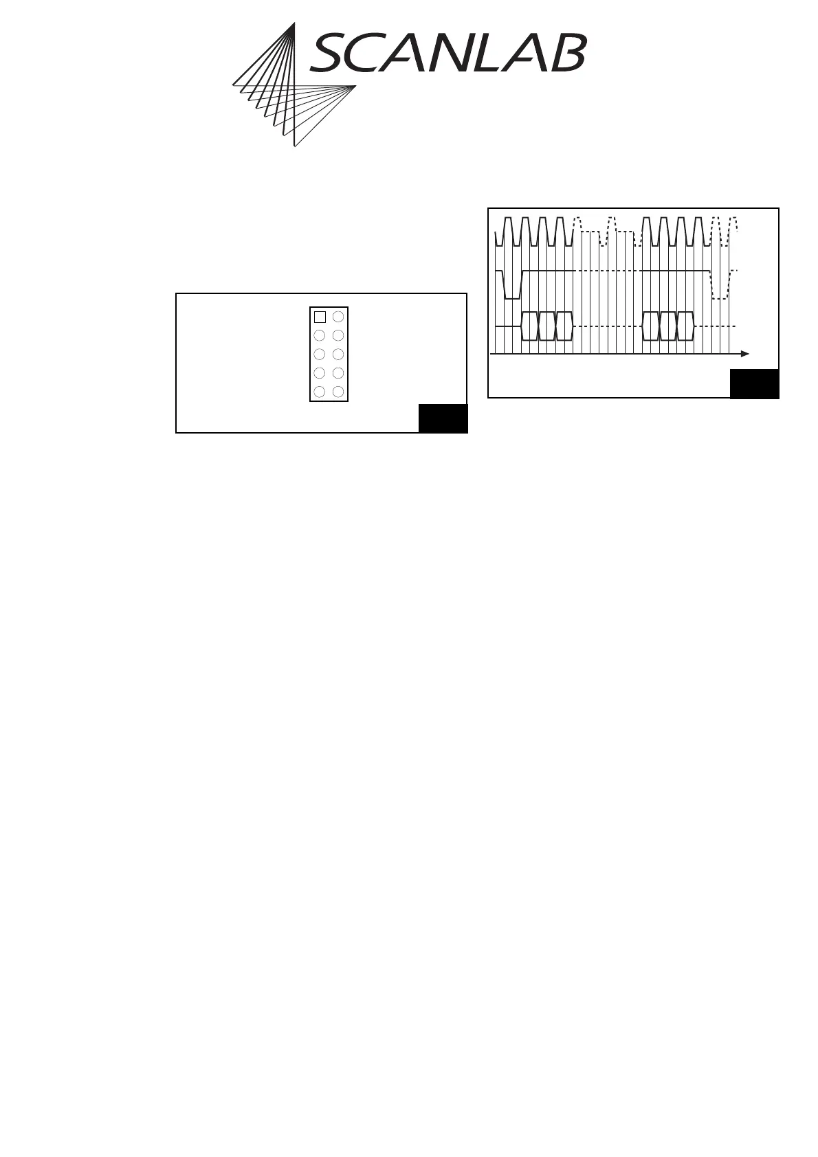
• The pulse diagram of the McBSP signals is shown
in figure 22. An active-low FrameSync pulse is
generated upon the clock’s rising edge and held
for one data bit. With the clock’s next 32 rising
edges, the next 32 data bits are transmitted in the
sequence Bit31…Bit0. The default transmission
frequency (after initialization) is 8 MHz (4 µs per
data word), but the transmission frequency can
also be set to between 4 MHz and 16 MHz via
set_mcbsp_freq.
•The set_mcbsp_out and set_mcbsp_out_ptr
commands lets you select the data signals to be
transmitted. The signals are continuously trans-
mitted every 10 µs.
21
SCL (1)
CLKX0 (3)
FSX0 (5)
DX0 (7)
GND (9)
(2) SDA
(4) CLKR0
(6) FSR0
(8) DR0
(10) 3.3 V
Pin-out of the (on-board) “SPI / I2C” connector
DX/R
CLKX/R
FSX/R
t
B31 B30 B29 B2 B1 B0
Pulse diagram of McBSP interface for DataDelay = 1