RTC
®
5 PC Interface Board
Rev. 1.9 e
15 Appendix A: The RTC
®
5 PC/104-Plus Board
579
15.2.2 Interface to the CPU board
Data transfer between the CPU board and the
RTC
®
5 PC/104-Plus board is via the PCI bus. The
RTC
®
5 PC/104-Plus board provides 120-pin PCI stack-
through connectors (see figure 61 on page 577). The
timing and signal levels of the PCI signals are in
compliance with PCI Local Bus Specification
Revision 2.2. 64-bit extensions, JTAG, PRSNT and
CLKRUN signals are not supported.
On the ISA bus, the RTC
®
5 PC/104-Plus board only
uses the +5 V power provided at pins B3, B29 and
D16 (for more power supply information, also see
page 585). The other signals of the ISA bus are simply
forwarded via the 104-pin ISA stack-through
connectors to further boards in the stack and are not
used by the RTC
®
5 PC/104-Plus board.
15.2.3 Master/Slave Synchronization
If multiple synchronously-clocked RTC
®
5 PC/104-Plus
boards are to be used in a PC/104 stack, then the
RTC
®
5 PC/104-Plus boards must be connected
pairwise with each other via the MASTER and SLAVE
connectors and installed in adjacent stack positions.
Always connect a board’s MASTER connector to the
SLAVE connector of another board. Suitable
connection cables are available from SCANLAB.
Also see chapter 6.6.3 "Master/Slave Operation",
page 84 and "Starting and Stopping Lists via External
Control Signals and Master/Slave Synchronization",
page 209.
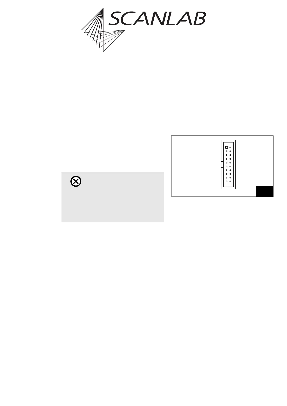
15.2.4 Interfaces to Scan System
For digitally controlling scan systems, the 20-pin
SCANHEADS connector provides the primary scan
head connection (pins 1 through 10) and the
optionally activated secondary scan head connection
(pins 11 through 20) (see figure 61 on page 577). At
this connector, scan-system control values are trans-
mitted and scan-system status signals received.
Figure 63 shows the pin-out of the SCANHEADS
connector.
The SCANHEADS connector provides the same signals
as the SCAN HEAD and 2. SCAN HEAD connectors of
the RTC
®
5 PC interface board. Scan system control
(via an XY2-100 converter, if needed) is identical to
that of the RTC
®
5 PC interface board. Note the infor-
mation in chapter 4.3 "Interfaces to Scan System",
page 41.
Caution!
•The RTC
®
5 PC/104-Plus board does not support
power-saving modes that switch off power to
the PCI bus. Accordingly, you must disable
standby or sleep modes of the operating
system. Also see the note on page 27.
63
DATA IN 1+ (1)
+3.3 V (DO NOT CONNECT) (3)
NOT CONNECTED (5)
NOT CONNECTED (7)
DATA OUT 1+ (9)
DATA IN 2+* (11)
+3.3 V (DO NOT CONNECT) (13)
NOT CONNECTED (15)
NOT CONNECTED (17)
DATA OUT 2+* (19)
(2) DATA IN 1 –
(4) GND
(6) GND
(8) DATA OUT 1 –
(10) NOT CONNECTED
(12) DATA IN 2 – *
(14) GND
(16) GND
(18) DATA OUT 2 – *
(20) NOT CONNECTED
Pin-out of the SCANHEADS connector
(* Signal only optionally activated)