Legend
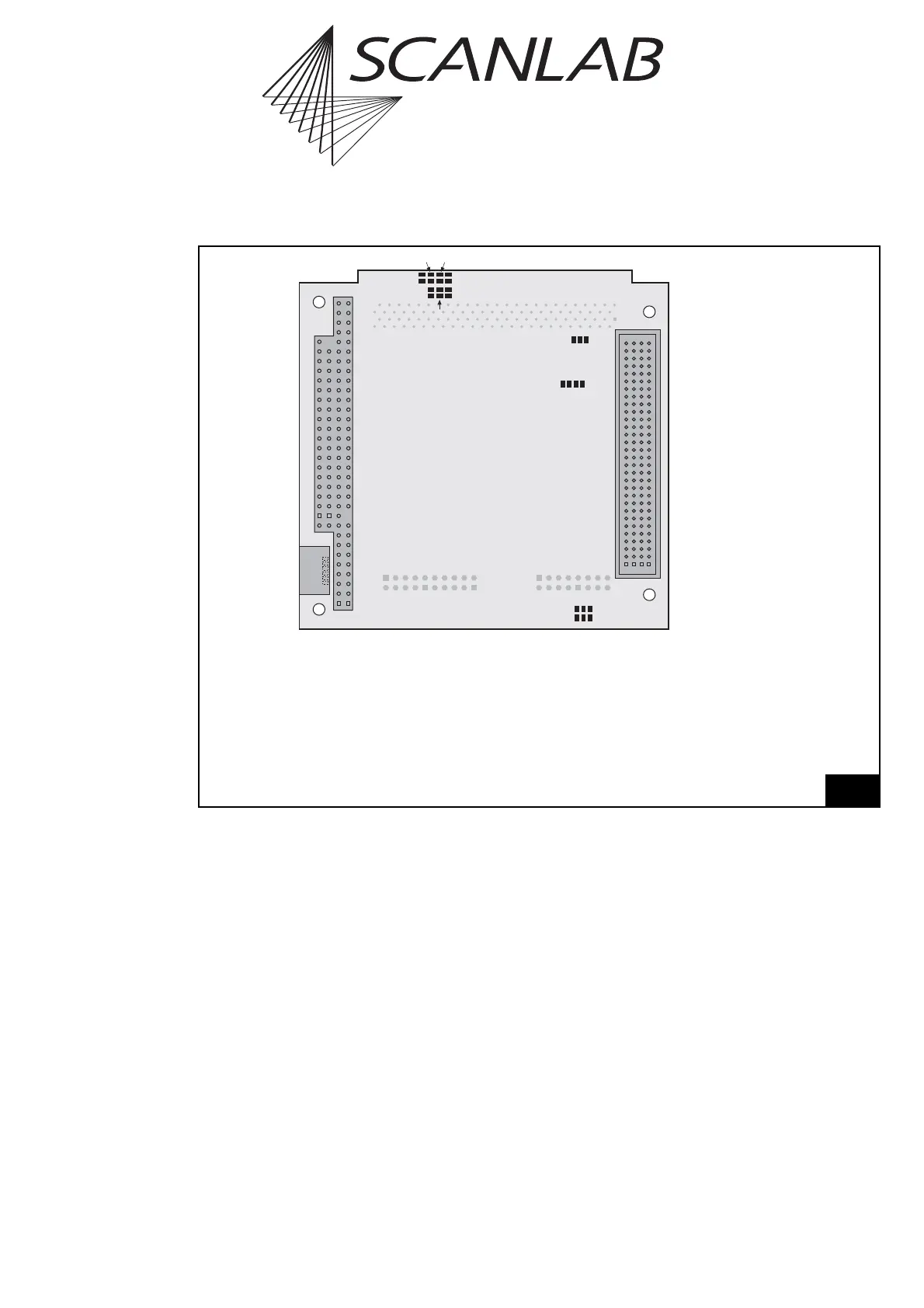
Master . . . . . . 6-pin MASTER connector (see "Master/Slave Synchronization", page 579)
JP1 . . . . . . . . . Jumper for selecting the output signal level at the MULTI connector (see page 586)
JP2 - JP8 . . . . . Jumpers for configuring Pin B40 and B42 of the MULTI connector (see page 586)
JP10+JP12 . . . Jumpers for setting how the 10 V maximum output voltage is generated at the
analog outputs ANALOG OUT1 and ANALOG OUT2 on the MULTI connector (see
page 585)
JP17+JP18 . . . Jumpers for setting the binary stack address, i.e. for electrical configuration of the
board for its position in the stack (see page 584)
62