RTC
®
5 PC Interface Board
Rev. 1.9 e
7 Basic Functions for Scan Head and Laser Control
102
Mark Delay
Although the marking speed is usually lower than
the jump speed, a lag between the set position and
the real position occurs not only during a jump, but
also during a mark or arc command. Also a small
settling time can be necessary for the mirrors to reach
the set position.
To make sure that the scanners reach the final
set position properly before the next command
starts, the RTC
®
5 inserts a mark delay after a single
mark or arc command or after the last mark or arc
command of a polyline (see figure 32).
Notes
• If a mark or arc command is not followed by
further mark or arc commands, then a mark delay
will be inserted and the laser will be switched off
(after a LaserOff delay) (see figure 32).
• If a mark or arc command is directly followed by
a further mark or arc command, then a polygon
delay or a variable polygon delay will be inserted
instead of a mark delay (see figure 33 on
page 103 and figure 35 on page 105). The laser
will then remain on unless a correspondingly
smaller
edgelevel
was set with set_delay_mode
or set_delay_mode_list (see page 104).
• Mark or arc commands with a length of zero that
execute with switched-on “laser active” laser
control signals (i.e. within a polyline)
– are short list commands (if not timed for an
execution duration > 5 µs, see below). They
will not interrupt a polyline even when several
such commands directly follow each other.
– will be ignored in calculating delays (as of
RTC5OUT.out version 515): The mark delay or
(variable) polygon delay executes in accordance
with the commands that directly precede or fol-
low the zero-length command(s). If the com-
mand is executed individually (i.e. not within a
polyline), then no mark delay will be per-
formed.
– do not change the laser control signals (as of
RTC5OUT.out version 518): if the laser is still off,
then it won’t be switched on; likewise, if the
laser is already on, then it will remain on.
• But if a mark or arc command of zero length
executes with switched-off “laser active” laser
control signals (i.e. as a single command or at the
start of a polyline), then it will behave (as of
RTC5OUT.out Version 527) as a timed mark or arc
command with an execution time of 10 µs (see
following note).
• Timed mark or arc commands with zero spacial
length (as of RTC5OUT.out version 526 and if the
specified execution duration is > 5 µs) behave like
mark or arc commands of finite spacial length:
– If necessary, the laser control signals will be
switched on (at the beginning of a polyline)
and off (at the end of a polyline).
– Mark and polygon delays will execute (but vari-
able polygon delays are always 0).
– These commands will require at least a 10 µs
clock cycle for execution.
Notes on earlier versions
• With RTC5OUT.out version up to 514, only the
subsequent mark delay or (variable) polygon delay of a
zero-length mark or arc command is suppressed for a
zero-length mark or arc command; but the preceding
one is executed (a preceding (variable) polygon delay is
executed as a mark delay).
• With RTC5OUT.out version up to 517, the laser is
switched on after a LaserOn delay for zero-length mark
or arc commands (as is usual for mark or arc commands
with a length greater than 0).
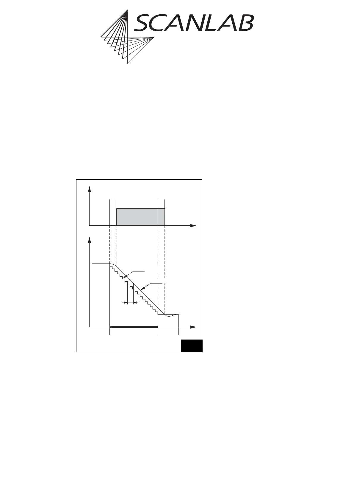
Time
LaserPosition
Set Position
LaserOn
Delay
LaserOff
Delay
Mark
Command
Mark
Delay
Real Position
Tracking
Error
Scan head and laser control timing during a mark or arc command
with a mark delay. Grey shaded areas indicate that the laser is on.