and back side. All connectors and jumper settings are
described in detail in the following sections.
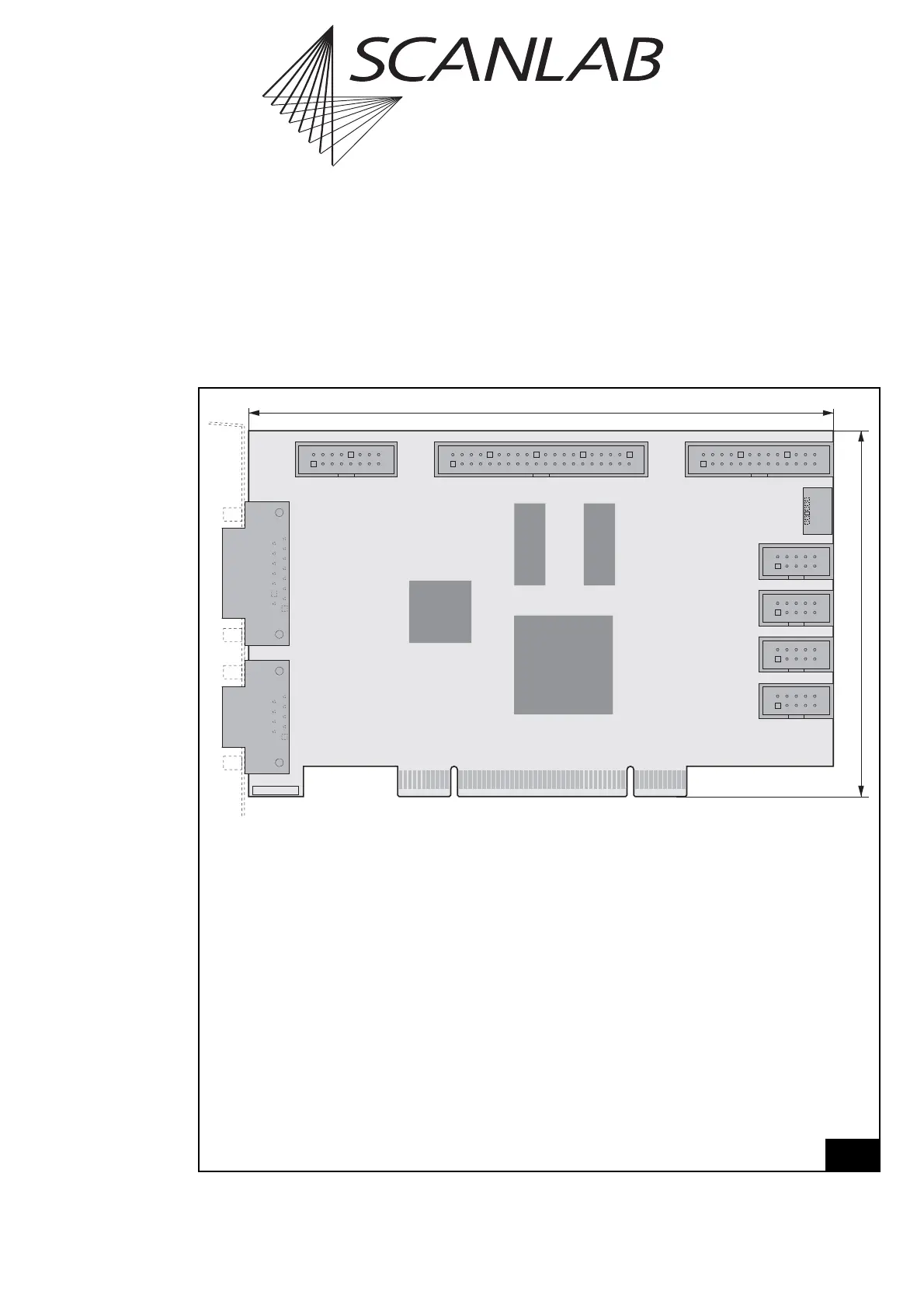
Legend
SCAN HEAD . . . . . . . . . . . . Primary scan head connector (D-SUB 9-pin female, pin-out see page 41)
LASER. . . . . . . . . . . . . . . . . Laser connector and digital and analog output ports (D-SUB 15-pin female,
pin-out see page 46)
MARKING ON THE FLY . . . . 16-pin socket connector with encoder inputs, (optionally) for Processing-on-
the-fly applications (pin-out see page 51)
EXTENSION 1 . . . . . . . . . . . 40-pin socket connector with a 16-bit digital input and a 16-bit digital output
(pin-out see page 49)
EXTENSION 2 . . . . . . . . . . . 26-pin socket connector with an 8-bit digital output port, e.g. for alternative
laser control (pin-out see page 50)
SLAVE. . . . . . . . . . . . . . . . . 6-pin SLAVE connector (see "Master/Slave Synchronization", page 40)
2. SCAN HEAD . . . . . . . . . . 10-pin socket connector for secondary scan head control (optionally acti-
vated, pin-out see page 41)
STEPPER MOTOR . . . . . . . . 10-pin socket connector for stepper motor control (pin-out see page 53)
RS232 . . . . . . . . . . . . . . . . 10-pin socket connector for controlling external devices via RS232 interface
(pin-out see page 51)
SPI / I2C . . . . . . . . . . . . . . . 10-pin socket connector (serial extension interface, pin-out see page 52)
ID . . . . . . . . . . . . . . . . . . . . ID number
PCI Connector . . . . . . . . . . Interface to PC (see page 40)
2