RTC
®
5 PC Interface Board
Rev. 1.9 e
15 Appendix A: The RTC
®
5 PC/104-Plus Board
580
15.2.5 Interfaces for the Laser and
Peripheral Equipment
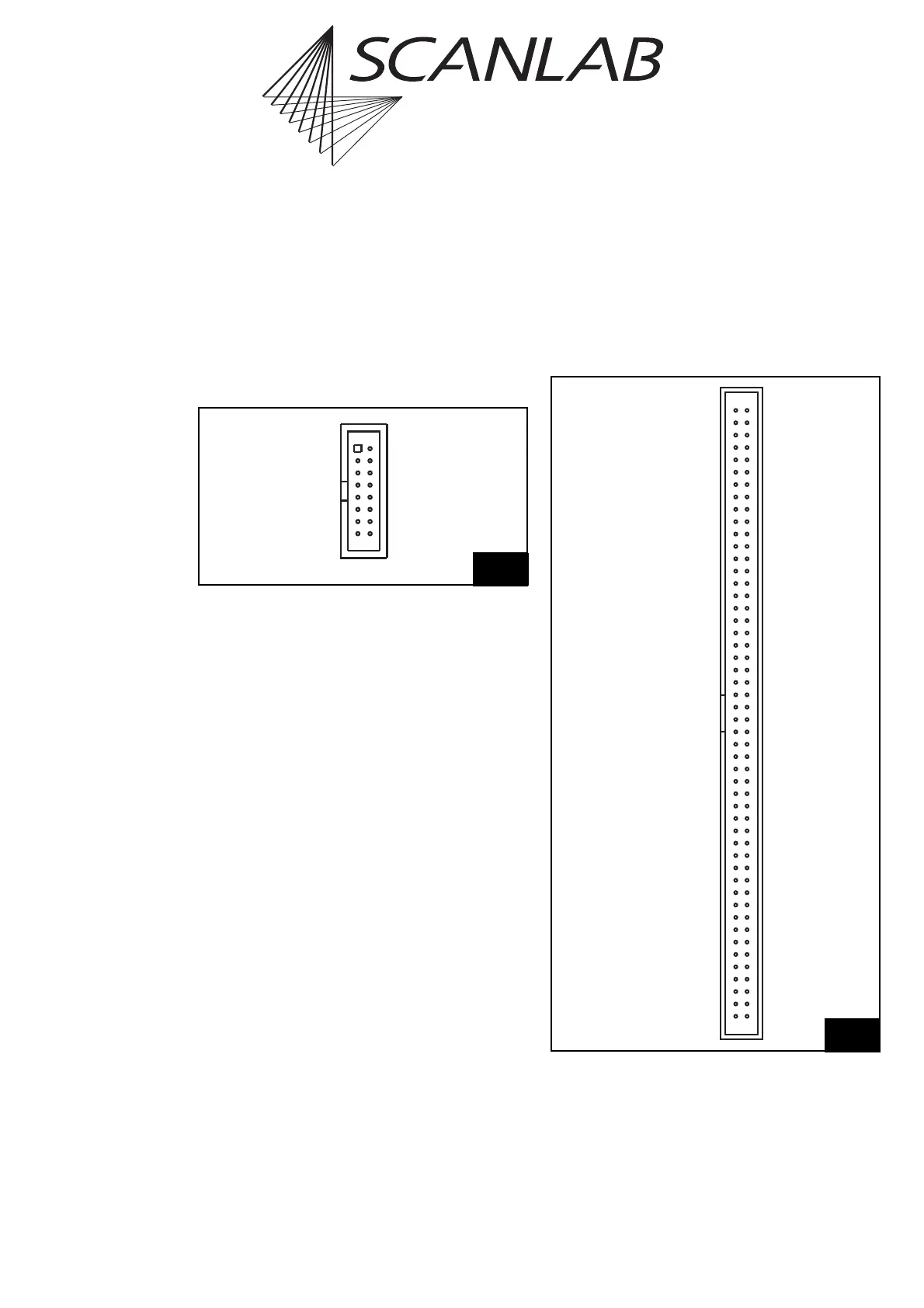
LASER connector
Figure 64 shows the pin-out of the 16-pin LASER
connector. This connector provides the same signals
as the 15-pin D-SUB LASER connector of the
RTC
®
5 PC interface board. Note the information in
"Laser Connector", page 46.
The connector provides the two analog output ports
ANALOG OUT1 and ANALOG OUT2 (the
ANALOG OUT2 signal is also available via the MULTI
connector, see figure 65). Jumpers JP10+JP12 on the
back side of the RTC
®
5 PC/104-Plus board allow
setting how the 10 V maximum output voltage of
these analog outputs is generated (see page 585).
A slot cover with a 15-pin D-SUB connector for using
the inputs and signals of the LASER connector (with
the same pin-out as the 15-pin D-SUB LASER
connector of the RTC
®
5 PC interface board, see
figure 10 on page 46) is available from SCANLAB.
MULTI connector
Figure 65 shows the pin-out of the 100-pin MULTI
connector. This multifunction connector provides the
same signals as the EXTENSION 1, EXTENSION 2,
MARKING ON THE FLY, ”RS232”, “STEPPER MOTOR”
and “SPI / I2C” connectors on the RTC
®
5PCinterface
board. Note the information in the following table.
64
(2) LASER2
(4) GND2
(6) /STOP
(8) DIGITAL OUT1
(10) DIGITAL IN1
(12) GND
(14) ANALOG OUT2*
(16) NOT CONNECTED
LASER1 (1)
LASERON (3)
/START (5)
BUSY OUT (7)
DIGITAL OUT2 (9)
DIGITAL IN2 (11)
+5 V (13)
ANALOG OUT1* (15)
Pin-out of the 16-pin LASER connector
(* depends on jumper settings JP10 and JP12)
(A1) DIGITAL OUT0
#
(A2) DIGITAL IN0
(A3) DIGITAL OUT1
#
(A4) DIGITAL IN1
(A5) DIGITAL OUT2
#
(A6) DIGITAL IN2
(A7) DIGITAL OUT3
#
(A8) DIGITAL IN3
(A9) DIGITAL OUT4
#
(A10) DIGITAL IN4
(A11) DIGITAL OUT5
#
(A12) DIGITAL IN5
(A13) DIGITAL OUT6
#
(A14) DIGITAL IN6
(A15) DIGITAL OUT7
#
(A16) DIGITAL IN7
(A17) DIGITAL OUT8
#
(A18) DIGITAL IN8
(A19) DIGITAL OUT9
#
(A20) DIGITAL IN9
(A21) DIGITAL OUT10
#
(A22) DIGITAL IN10
(A23) DIGITAL OUT11
#
(A24) DIGITAL IN11
(A25) DIGITAL OUT12
#
(A26) DIGITAL IN12
(A27) DIGITAL OUT13
#
(A28) DIGITAL IN13
(A29) DIGITAL OUT14
#
(A30) DIGITAL IN14
(A31) DIGITAL OUT15
#
(A32) DIGITAL IN15
(A33) LATCH OUT
#
(A34) SYNC OUT
#
(A35) VCC OUT
#
(A36) BUSY OUT
#
(A37) +5 V
(A38) +5 V
(A39) GND
(A40) GND
(A41) CLKX0
(A42) CLKR0
(A43) FSX0
(A44) FSR0
(A45) DX0
(A46) DR0
(A47) +3.3 V
(A48) GND
(A49) RxD
(A50) TxD
65
+5 V (B1)
GND (B2)
ENCODER X1 – (B3)
ENCODER X1+ (B4)
ENCODER X2 – (B5)
ENCODER X2+ (B6)
ENCODER Y1 – (B7)
ENCODER Y1+ (B8)
ENCODER Y2 – (B9)
ENCODER Y2+ (B10)
/STOP2 (B11)
/START2 (B12)
BUSY OUT (B13)
ANALOG OUT2* (B14)
GND (B15)
SWITCH1 (B16)
SWITCH2 (B17)
ENABLE1 (B18)
ENABLE2 (B19)
DIRECTION1 (B20)
DIRECTION2 (B21)
CLOCK1 (B22)
CLOCK2 (B23)
GND (B24)
GND (B25)
DATA0 (B26)
NOT CONNECTED (B27)
DATA1 (B28)
NOT CONNECTED (B29)
DATA2 (B30)
NOT CONNECTED (B31)
DATA3 (B32)
NOT CONNECTED (B33)
DATA4 (B34)
NOT CONNECTED (B35)
DATA5 (B36)
NOT CONNECTED (B37)
DATA6 (B38)
NOT CONNECTED (B39)
+5 V /DATA7 / GND
§
(B40)
NOT CONNECTED (B41)
+5 V/DATA7/GND/LATCH
§
(B42)
+5 V (B43)
LASER2 (B44)
(B46) (B45)
(B45) (B46)
LASER1 (B47)
GND2 (B48)
NOT CONNECTED (B49)
+5 V (B50)
Pin-out of the 100-pin MULTI connectors
(* depends on JP10 and JP12 jumper settings
§
depends on JP2-JP8 jumper settings
#
Output signal level depends on JP1 jumper setting)