RTC
®
5 PC Interface Board
Rev. 1.9 e
4 Layout and Interfaces
43
The data channels CHAN1 and CHAN2 transmit
control values to the scan head. The SYNC and CLOCK
channels transmit synchronization and clock signals
to the scan system. The STATUS channel (and, if
appropriate, the STATUS1 channel) receives XY2-100
compliant status signals returned by the scan system.
If very long cables are used for data transmission
between the XY2-100 converter and the scan system,
then the synchronization of bidirectional communi-
cation between the scan system and the RTC
®
5
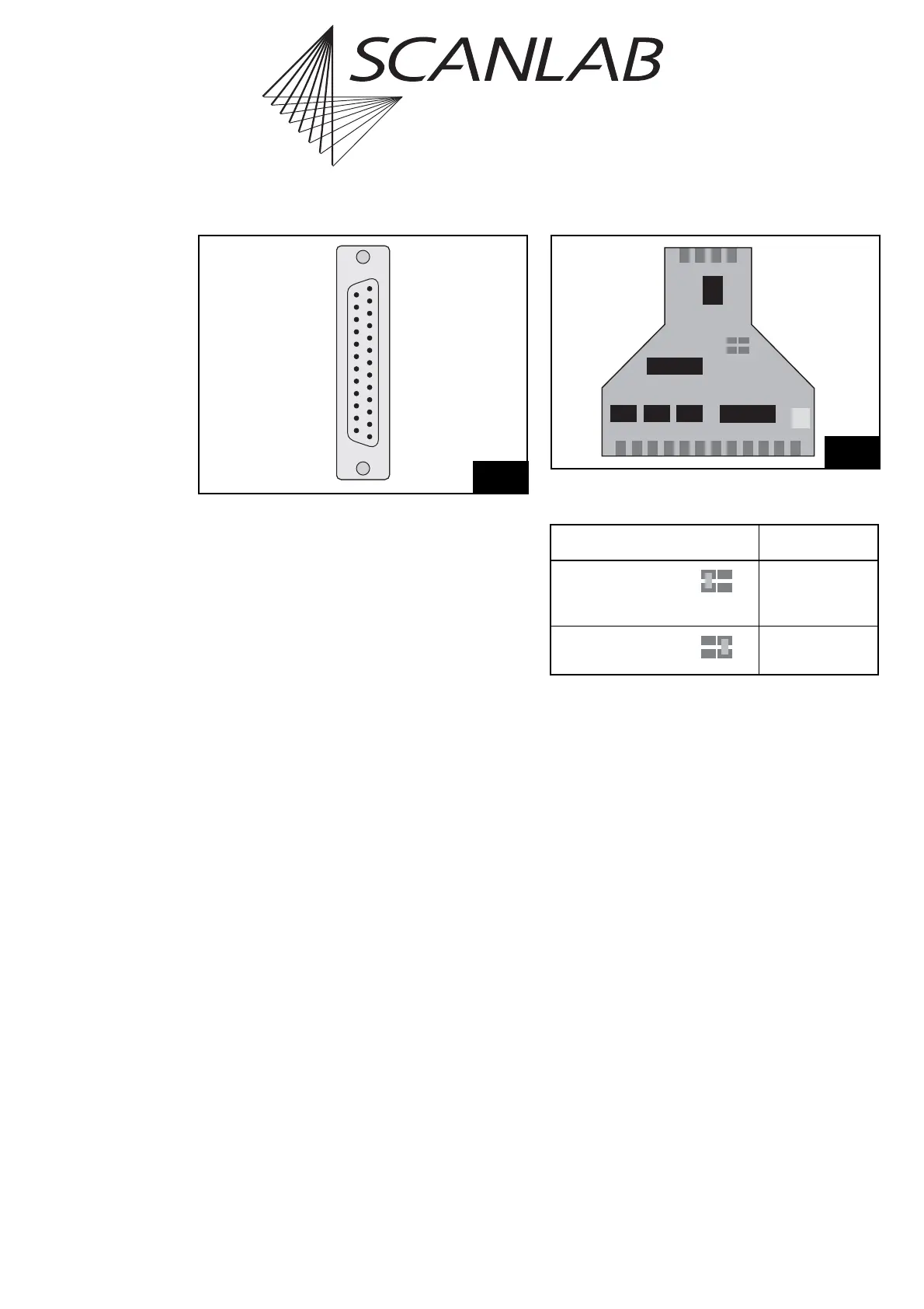
should be configured. This can be accomplished via
two solder jumpers in the XY2-100 converter. To do
so, carefully open the converter’s housing via its four
clip latches (e.g. using a screwdriver). The solder
jumpers JP1 and JP2 are on the converter’s PCB,
between the two D-SUB connectors. Figure 8 shows
the positions of the jumpers on the PCB. The table
below lists the possible jumper settings and the
corresponding cable lengths. Other jumper settings
as well as cable lengths above 25 m are not recom-
mended.
7
(13) DO NOT CONNECT
(12) DO NOT CONNECT
(11) DO NOT CONNECT
(10) DO NOT CONNECT
(9) DO NOT CONNECT
(8) STATUS1 – *
(7) DO NOT CONNECT
(6) STATUS – *
(5) DO NOT CONNECT
(4) CHAN2 –
(3) CHAN1 –
(2) SYNC –
(1) CLOCK –
DO NOT CONNECT (25)
DO NOT CONNECT (24)
DO NOT CONNECT (23)
DO NOT CONNECT (22)
* STATUS1+ (21)
DO NOT CONNECT (20)
* STATUS+ (19)
DO NOT CONNECT (18)
CHAN2+ (17)
CHAN1+ (16)
SYNC+ (15)
CLOCK+ (14)
Pin-out of the XY2-100 converter’s 25-pin female D-SUB
connector
* For iDRIVE
®
scan systems (intelliSCAN
®
, intelliSCAN
de
®
,
intelliDRILL
®
, intellicube
®
, intelliWELD
®
, varioSCAN
de
), the
STATUS± channel is the status channel of axis 2 (X axis; this
channel is then also called STATUS2±) and the STATUS1± channel
is the status channel of axis 1 (Y axis). For other scan systems, the
STATUS1± channel can not be used: “DO NOT CONNECT”.
Jumper Cable length *
JP1 closed
(default
configuration)
0m to 20m
JP2 closed 20 m to 40 m
Positions of solder jumpers JP1 and JP2 on the PCB of the XY2-100
converter
* For each jumper configuration, the recommended cable length
range depends – among others – on the used cable type and can
differ from the values listed above.