4.105
Date Code 20150130 Instruction Manual SEL-787 Relay
Protection and Logic Functions
Front-Panel Settings (SET F Command)
Rotating Display
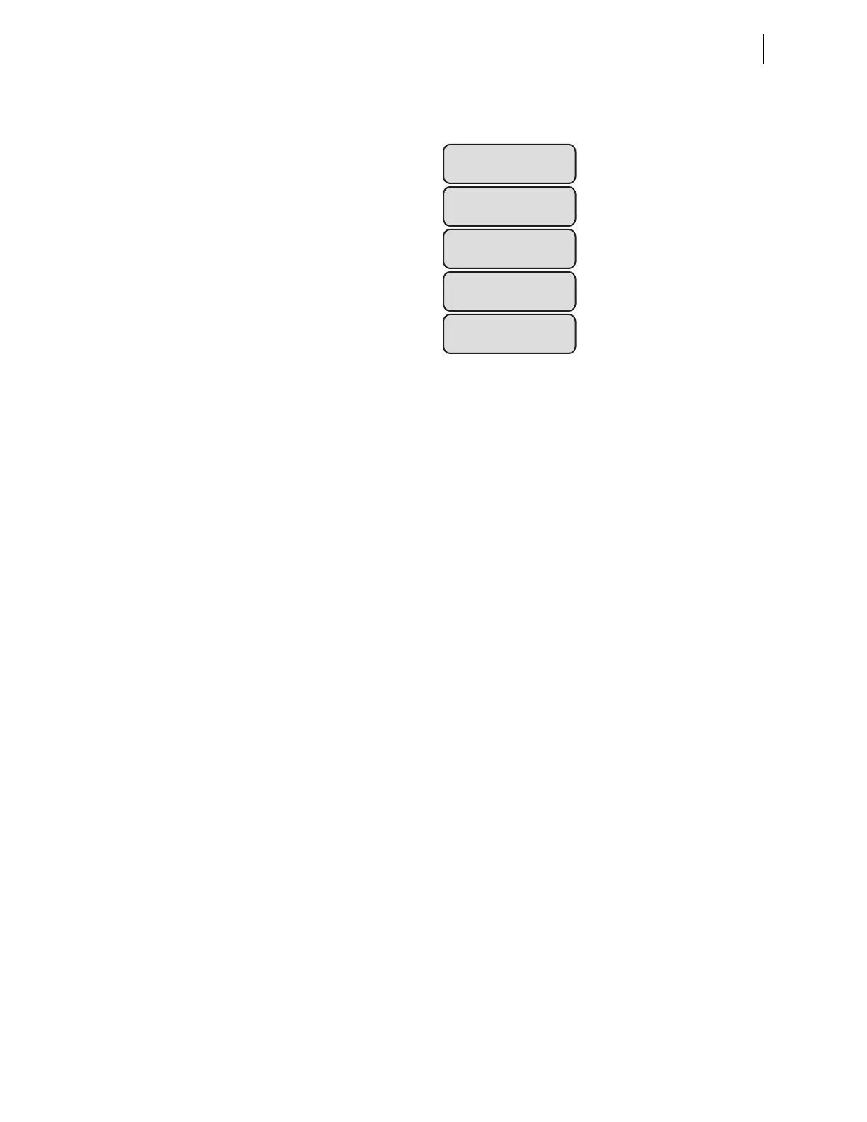
With more than two display points enabled, the relay scrolls through all
enabled display points, thereby forming a rotating display, as shown in Figure 4.79.
Figure 4.79 Rotating Display
To change the temperature units to more descriptive engineering units, enter
the desired units with the AIxxxEU (e.g., AI302EU) setting.
Local Bits
Local bits are variables (LBnn, where nn means 01 through 32) that are
controlled from front-panel pushbuttons. Use local bits to replace traditional
panel switches. The state of the local bits is stored in nonvolatile memory
every second. When power to the device is restored, the local bits will go back
to their states after the device initialization.
Each local bit requires three of the following four settings, using a maximum
of 14 valid characters for the NLBnn setting, and a maximum seven valid
characters (0–9, A–Z, -, /, ., space) for the remainder:
➤ NLBnn: Name the switch (normally the function that the
switch performs, such as SUPERV SW) that will appear on the
LCD display.
➤ CLBnn: Clear local bit. Enter the text that describes the
intended operation of the switch (this text appears on the
display) when LBnn deasserts (OPEN, for example).
➤ SLBnn: Set local bit. Enter the text that describes the intended
operation of the switch (this text appears on the display) when
LBnn asserts (CLOSE, for example).
➤ PLBnn: Pulse local bit. When selecting the pulse operation,
LBnn asserts for only one processing interval before
deasserting again. Enter the text that describes the intended
operation when LBnn asserts (START, for example).
➤ Omit either SLBnn or PLBnn (never CLBnn) by setting the
omitted setting to NA.
For the transformer in our example, configure two local bits: one to replace a
supervisory switch, and the other to start a fan motor. Local bit 1 replaces a
supervisory switch (SUPERV SW) and we use the clear/set combination.
Local bit 2 starts a fan motor (START) that only needs a short pulse to seal
itself in, and we use the clear/pulse combination. Figure 4.80 shows the
settings to program the two local bits.
TRFR 1 HV BRKR:=
TRFR 1 LV BRKR:=
Screen 1
HOT SPOT TEMP
xxx.xx degrees C
Screen 2
OIL TEMPERATURE
0.031 mA
Screen 3
WINDING TEMP
0.037 mA
Screen 4
TRFR 1 HV BRKR:=
TRFR 1 LV BRKR:=
Screen 1