Installing cable fittings
Page 130 OmniTrax Product Guide
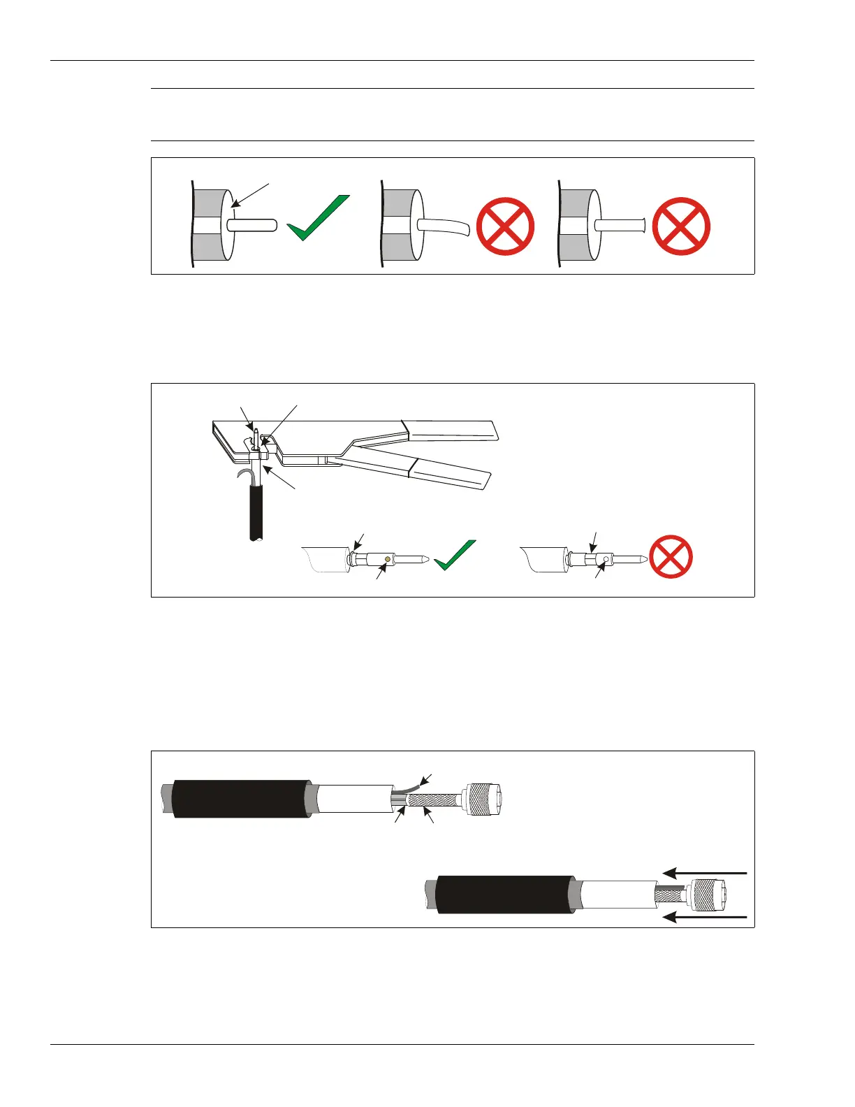
6. Push the center pin fully onto the center conductor. The center conductor must be visible
through the center pin’s inspection hole.
Using the smaller quad opening in the crimp tool, crimp the center pin once, as close to the
dielectric as possible. Do NOT crimp the shoulder of the center pin.
7. Slide the heatshrink over the end of the cable. Slide the crimp ring over the end of the cable
until it butts up against the gray jacket.
8. Lift the drain braid slightly and then fit the connector onto the sensor cable so the center pin,
dielectric core and foil covering fit smoothly inside the connector shell, and the drain braid
remains outside the connector shell.
Press the connector onto the cable until it clicks into place.
9. Slide the crimp ring over the connector shell and drain braid until it is flush against the head of
the connector.
Mark the location of the drain braid on the crimp ring.
Note Ensure that the center conductor is smooth (no lip or burr from cutting),
straight and 6 mm long.
There must be no foil on the flat cross section of the dielectric core.
Figure 103: Trimming the center conductor
Figure 104: Crimping the center pin
Figure 105: Fitting the connector
center
conductor is bent
no foil on dielectric
core cross section
smooth straight center
conductor (6 mm long)
burr on
center conductor
use the small quad opening
center pin
dielectric core
center pin shoulder
center conductor visible
center conductor not visible
crimp not close enough to dielectric core
drain braid
crimp ring
heat shrink
connector shell
foil and
dielectric core
press the connector onto the cable
until it clicks into place