Installing cable fittings
OmniTrax Product Guide Page 129
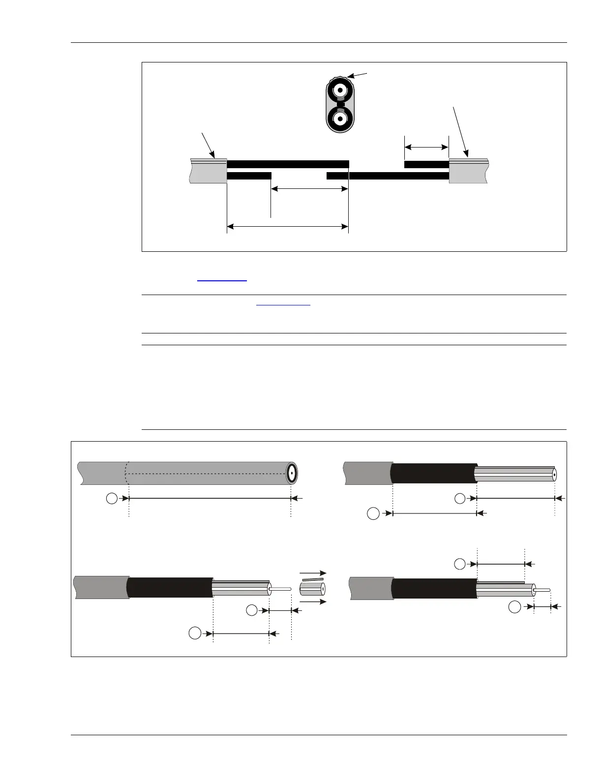
5. Refer to Figure 102: to prepare the sensor cables for connector installation.
Figure 101: Offsetting SC1 cables
Note
Figure 102: provides a 1:1 scale for stripping the sensor cables. Follow
the cable strip dimensions exactly, as the dimensions are critical to
connector installation.
Note When removing the black jacket, make the lengthwise score above the
drain braid. Do NOT cut into or through the drain braid.
Use pliers to peel back and remove the black jacket.
If you have difficulty removing the black jacket, try warming the jacket
with a few quick passes of a lighter. Heat the jacket only until it feels
warm to the touch, then peel the black jacket from the cable. Excessive
heat will damage the cable.
Figure 102: SC1/SC2 cable strip dimensions
SC1 sensor cable cross section
ridged surface on first SC1
sensor cable
ridged surface on second SC1
sensor cable
ridged surface
(short cable)
10 cm (4 in.)
offset the SC1 cables
15 cm (6 in.)
cut back from
end of cable
25 cm (10 in.)
(longer cable)
NOTE: For zone bypasses or cable splices
the long cable is 17 cm (6.7 in.) shorten the
remaining cable by 6 cm (2.5 in.).
1. Remove 58 mm of the gray outer jacket.
58 mm (2 9/32 in.)
2. Remove 28 mm of the inner black jacket.
28 mm (1 1/8 in.)
2b. Leave 30 mm of exposed black jacket.
30 mm (1 3/16 in.)
3. Remove 8 mm of the dielectric core and drain braid.
3b. Leave 20 mm of foil covered
dielectric core.
4. Trim the drain braid to 17 mm.
4b. Straighten the center conductor (if required)
and trim the center conductor to 6 mm.
8 mm (5/16 in.)
20 mm (25/32 in.)
(1/4 in.)
1:1 SCALE
17 mm
(11/16 in.)
6 mm