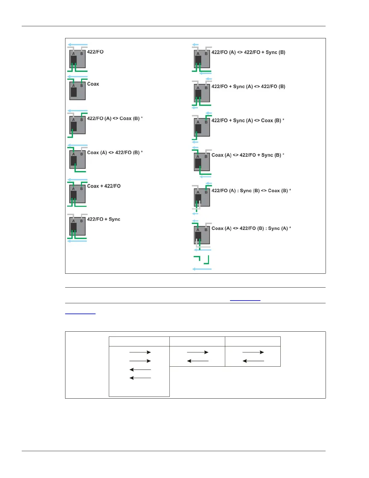
and fiber optic communication options. The arrows indicate the direction of data flow:
.
EIA-422, fiber optic or mixed media network
connection on sides A and B.
Synchronization done over sensor cables.
Sensor cable connection on sides A and B.
Synchronization done over sensor cables.
EIA-422 or fiber optic network connection on
side A and sensor cable connection on side B.
Synchronization done over sensor cables.
Sensor cable connection on side A and EIA-422
of fiber optic network connection on side B.
Synchronization done over sensor cables.
Sensor cable connection on sides A and B +
EIA-422 or fiber optic network connection data
tap on NIC.
Synchronization done over sensor cables.
*
Do not use a mixed media network interface card.
EIA-422, fiber optic or mixed media network
connection on sides A and B.
Synchronization done over 422/FO cables.
EIA-422, fiber optic or mixed media network
connection on sides A and B.
Synchronization done over sensor cable on
sides A and 422/FO cable on side B.
EIA-422, fiber optic or mixed media network
connection on sides A and B.
Synchronization done over 422/FO cable on
side A and sensor cable on side B.
EIA-422 or fiber optic network connection on
side A and sensor cable connection on side B.
Synchronization done over 422/FO cable on
side A and sensor cable on side B.
Sensor cable connection on side A and EIA-422
or fiber optic network connection on side B.
Synchronization done over sensor cable on
side A and 422/FO on side B.
Indicates direction and path for Synchronization.
Indicates Silver Network data flow.
EIA-422 or Fiber Optic network connection on
Synchronization received over B-Side Sensor
side A and sensor cable connection on side B.
cable and transmit on B-Side 422/FO cable.
Sensor cable connection on side A and EIA-422
or Fiber Optic network connection on side B
Synchronization received over A-Side 422/FO
cable and transmit on A-Side Sensor cable.