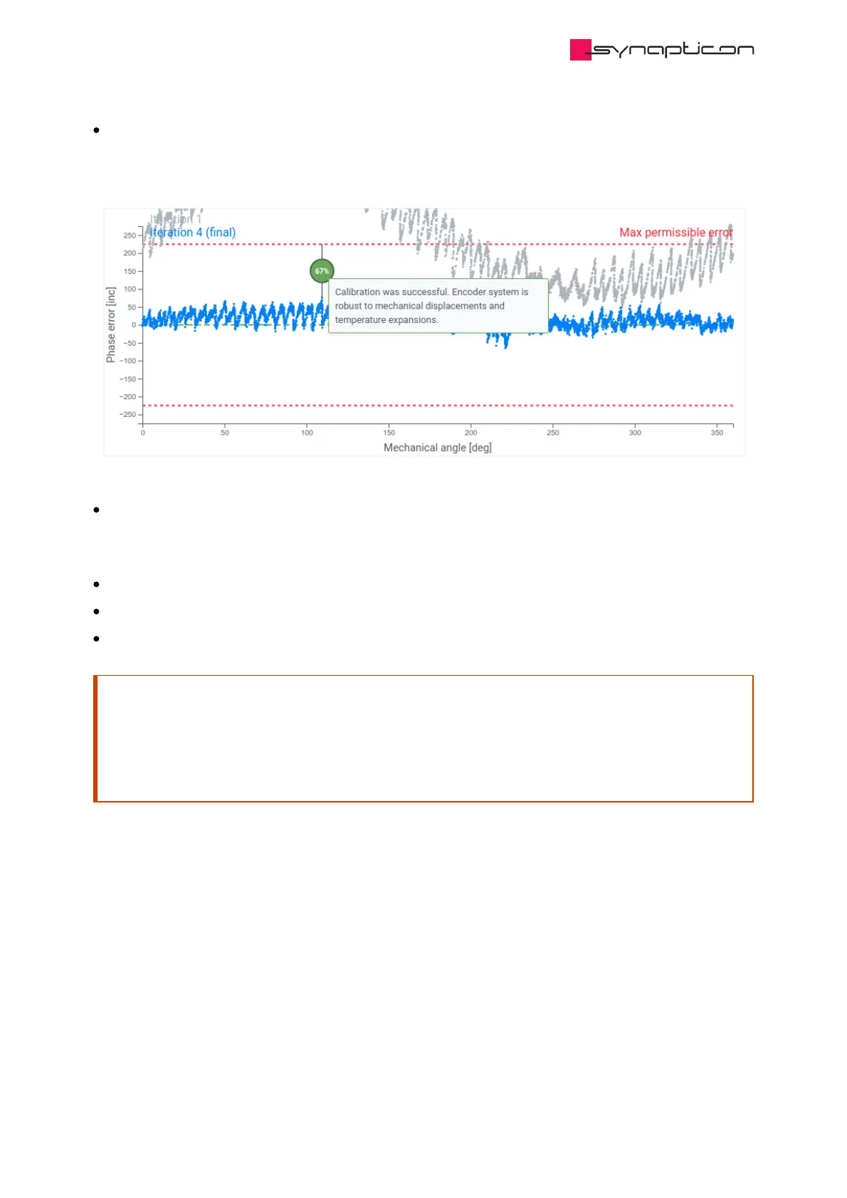
After the analog calibration procedure is successfully finished, check the estimated phase error plot. Note
the resulting phase error margin. Smaller margin results in more robust behavior of the encoder system:
small mechanical changes, vibration and temperature expansion are less likely to cause an error.
Additionally, if the magnetic target was damaged mechanically or magnetically, this will be visible from the
data as a single spike or an irregular error pattern.
After the optimal calibration parameters have been found:
Install the latest version of the firmware
Run Offset Detection again to find your optimized offset
Perform Velocity Tuning or Position Tuning (depending on the application)
Attention
The analog calibration procedure must be repeated when the mechanical position of the magnetic ring
has changed. This can also occur when mechanical wear has impaired the system performance.
An error will be triggered during startup in the Error Report Object 0x203F when the calibration is
required again: BisErBit
 Loading...

