EasyManuals Logo
Home>SYNAPTICON>Servo Drives>SOMANET Node Series

SYNAPTICON SOMANET Node Series User Manual

Default Icon
887 pages
To Next Page IconTo Next Page
To Previous Page IconTo Previous Page
Page #403 background imageLoading...
Page #403 background image
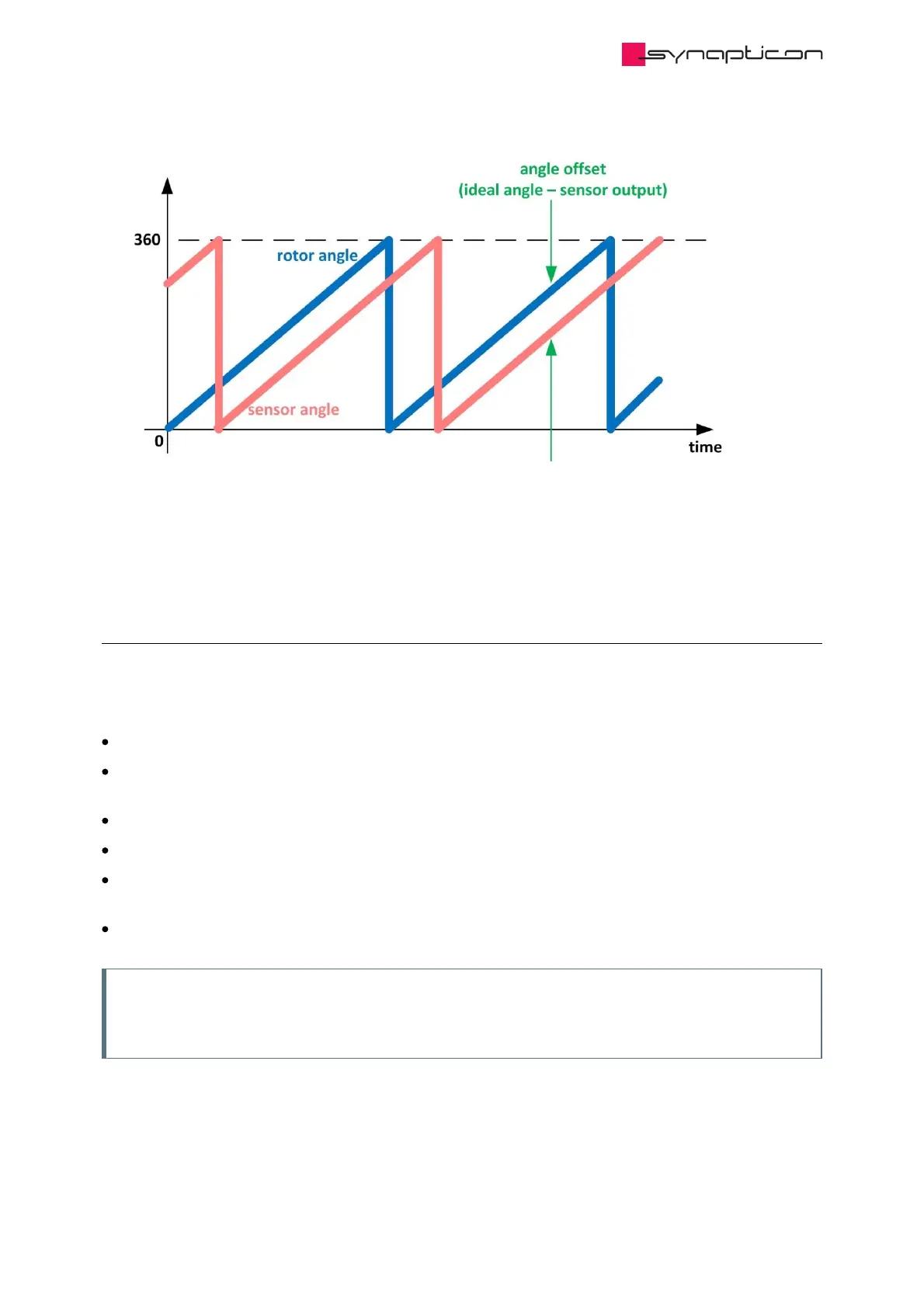
Fig. 3: In most of the cases, the provided sensor angle has a commutation angle
offset
3.1.3.5.3 Requirements
3.1.3.5.3.1 Load requirements
The active load of the system should be lower than motor rated torque
The position feedback sensor on the motor side should be configured properly and provide proper
feedback of the motor position
The motor should be configured correctly
The mechanical system should not block the motor
The brake should be configured correctly and work properly during the routine so that it doesn’t block the
system
The power supply used should be able to provide the voltage / current required by the routine
Note
If the requirements are not met, the Offset Detection routine fails and the detection result can be
wrong, leading to further failures.
Synapticon Documentation
© 2021 Synapticon GmbH | Daimlerstraße 26 | D-71101 Schönaich Documentation v 4.11.0 | Built 2021-07-23 403/887

Table of Contents

Other manuals for SYNAPTICON SOMANET Node Series

Questions and Answers:

Question and Answer IconNeed help?

Do you have a question about the SYNAPTICON SOMANET Node Series and is the answer not in the manual?

SYNAPTICON SOMANET Node Series Specifications

General IconGeneral
BrandSYNAPTICON
ModelSOMANET Node Series
CategoryServo Drives
LanguageEnglish

Related product manuals