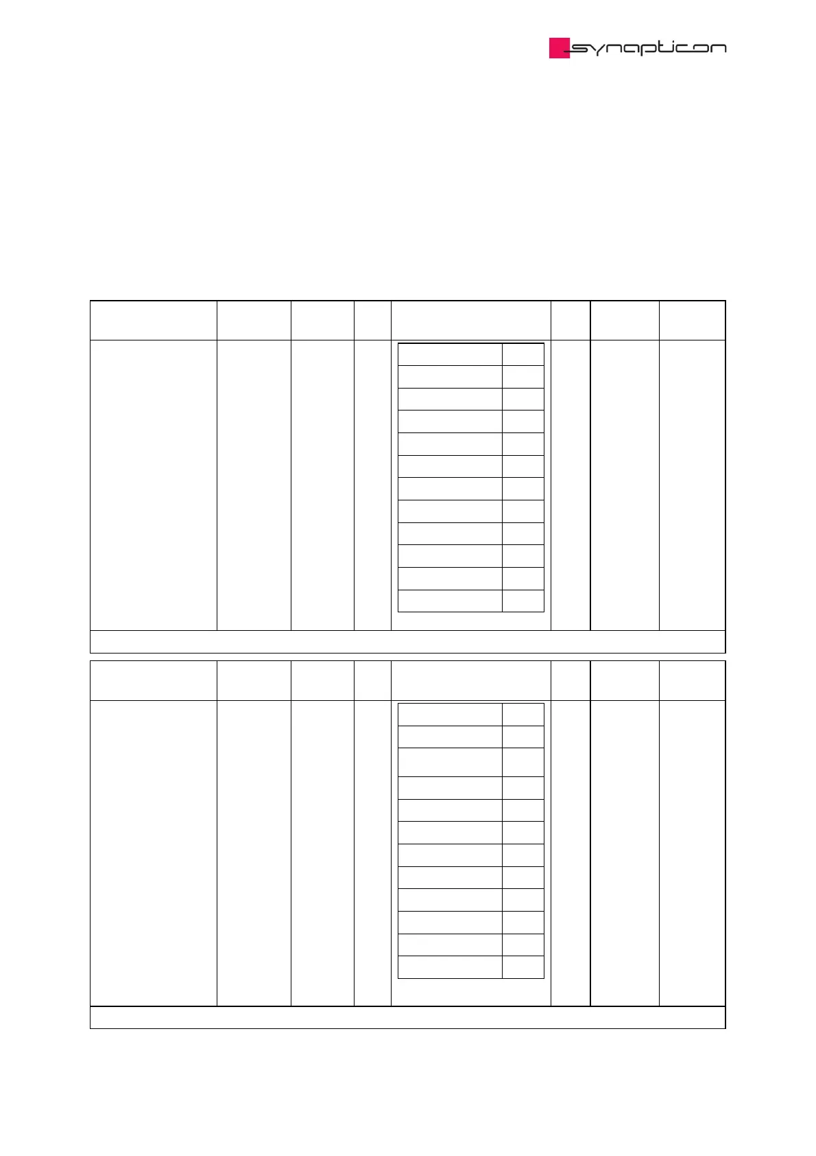
3.1.9.1.69 0x2100 Feedback sensor ports
Each connector ("port") can be associated with a sensor configuration object. Set the sub-items in this object to
a sensor configuration object index to associate the connector with that configuration.
For example, set 1:Sensor port 1 to the value 8709 (hex 0x2205) to tell the servo drive that an incremental
encoder (with the configuration as specified in object 0x2205 Incremental encoder 1 ) is mounted to the
first connector.
Name Index:Sub Type Bit
Size
Options Unit Access PDO
Mapping
Sensor port 1 0x2100:1 UINT 16
None 0
BISS 1 8705
BISS 2 8706
REM 16MT 8707
REM 14 8708
Incremental 1 8709
Incremental 2 8710
HALL 1 8711
HALL 2 8712
SSI 1 8713
SSI 2 8714
A-Format 8715
readwrite
Stores the index of the object containing sensor configuration.
Name Index:Sub Type Bit
Size
Options Unit Access PDO
Mapping
Sensor port 2 0x2100:2 UINT 16
None 0
BISS 1 8705
BISS 2 8706
REM 16MT 8707
REM 14 8708
Incremental 1 8709
Incremental 2 8710
HALL 1 8711
HALL 2 8712
SSI 1 8713
SSI 2 8714
A-Format 8715
readwrite
Stores the index of the object containing sensor configuration.
 Loading...

