3.1.8.2.1.3 Cyclic Synchronous Position Mode
The position control modes allow the EtherCAT master to send desired positions to the servo drive. The drive
will make sure these position values are reached by the motor (if the motor is physically able to do so).
In this mode, the trajectory generator is located in the control device, not in the servo drive. In a cyclic
synchronous manner, it provides a target position to the drive device, which performs position control, velocity
control and torque control.
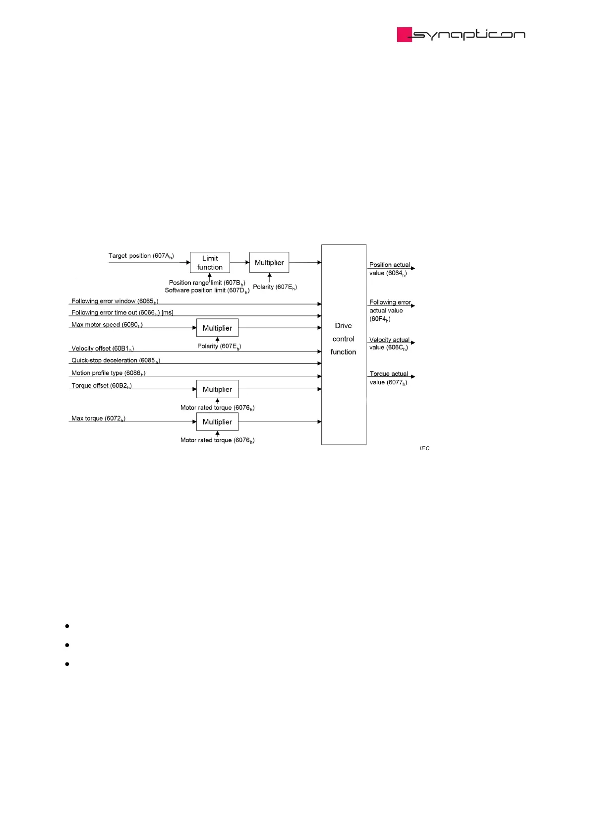
The figure above shows the inputs and outputs of the drive control function. The input values (from the
control function point of view) are the target position as well as an optional velocity offset and an optional
torque offset used for feed forward control. Especially in a cascaded control structure, where a position control
is followed by a velocity or torque control, the output of the position control loop is used as an input for
further calculation in the drive device. Limit functions can be used to restrict the range of values to avoid
unintended positions. The drive device monitors the following error.
The target position is interpreted as absolute value. The position actual value is used as mandatory output to
the control device. Further outputs are the velocity actual value and torque actual value. The following error
actual value is used as an additional parameter. See Control supervision for details.
Three control loops are implemented for position control:
Cascaded PID control
Simple PID control
Dual Encoder Cascaded Position Control.
 Loading...

