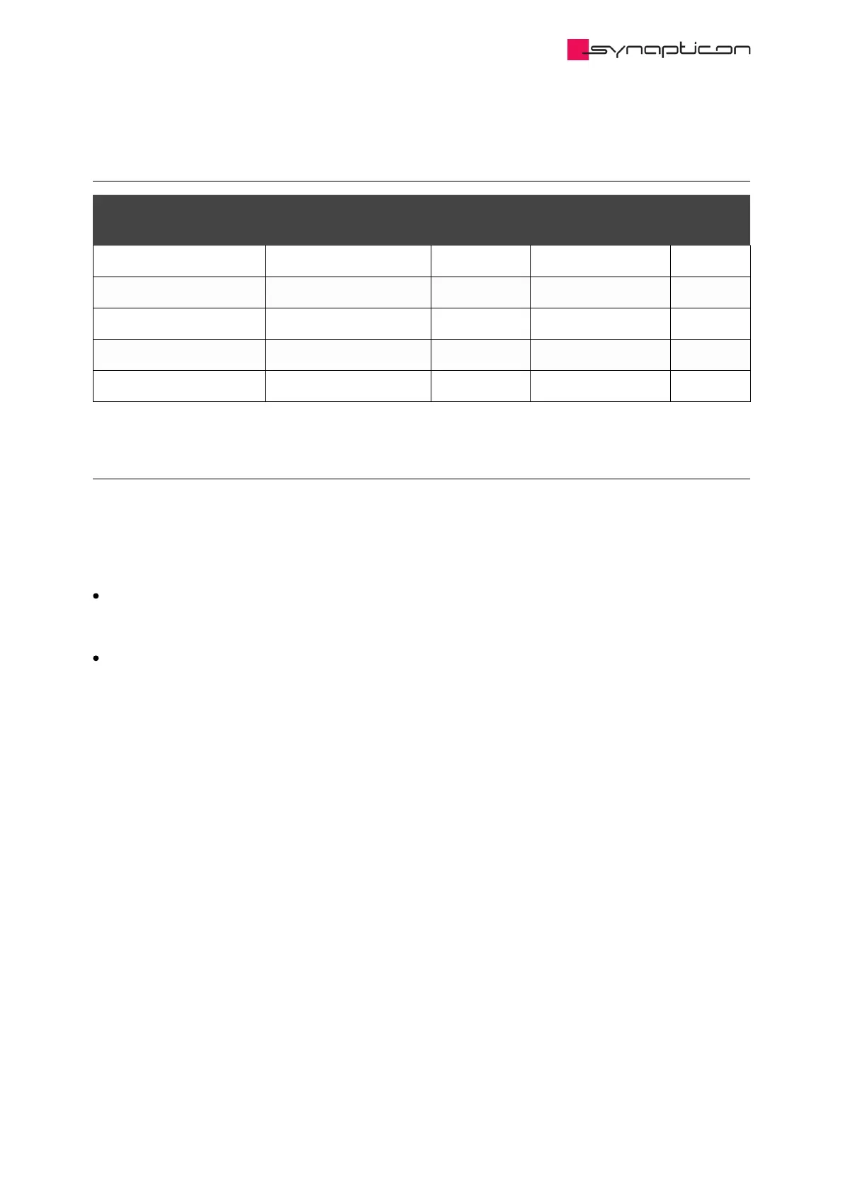
1.2.6.4.4.2 Truth table for digital inputs
Digital input STO-SBC 1 Digital input STO-SBC 2 Internal fault Safety Statusword Error
entry
0 0 no 1
0 1 no 1 “SfeDilvd”
1 0 no 1 “SfeDilvd”
1 1 no 0
0 0 yes 1 “SfeFault”
1.2.6.4.4.3 Diagnostic functions
1.2.6.4.4.3.1 Software diagnostics
The safety circuit has two integrated diagnostic functions:
Comparing safety digital input statuses. The fault is activated after 100ms discrepancy of the STO-SBC
inputs. In case a fault is detected, the servo drive will stop the motor and indicate a fault “SfeDilvd” in the
Error Report object.
During the activation of the STO-SBC function the servo drive verifies that the two channels of the module
are internally operating correctly. In case an internal fault is detected, the servo drive will stop the motor
and indicate a fault “SfeFault” in the Error Report object.
1.2.6.4.4.3.2 Hardware diagnostics
The STO-SBC feedback is a hardware feature that outputs a signal when both digital inputs have received the
STO-SBC signal correctly.
 Loading...

