1.2.6.2.3.2 Mounting tolerances
Assembling the encoder system in compliance with the following tolerances will allow to reach the specified
accuracy after the calibration procedures.
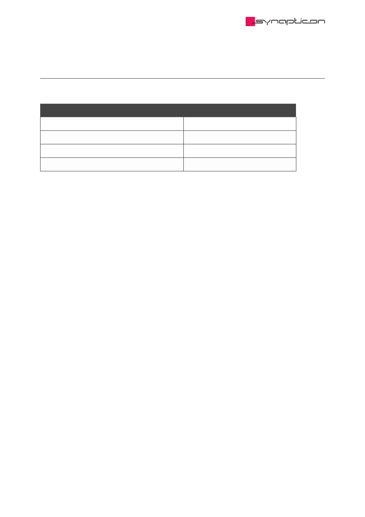
Parameter
Radial displacement r max 0.5 mm
Tangential displacement t max 0.5 mm
Axial distance (from disc to encoder chip) z 0.5 mm +/-0.1 mm
Mounting eccentricity (rotation axis offset) e max 0.1 mm
1.2.6.2.3.2.1 Radial displacement (r)
This basically means sliding the encoder chip off the scanning track. Deviations within the permissible range
increase the narrow angle error amplitude. This can be compensated by calibration. Moving the chip closer to
the center of the ring will have the the most effect due to a direct influence on the main positioning (Master)
track. The other direction will mostly reduce the absolute position accuracy. If increased more than specified
values, the chip might fail sensing the magnetic field and throw an error.
1.2.6.2.3.2.2 Tangential displacement (t)
This displacement is along the direction of the disc rotation. It is typically less crucial than the radial
displacement because the measured field doesn’t change as much along this axis. It reduces the absolute
position accuracy.
1.2.6.2.3.2.3 Axial distance
Mounting the chip closer than 0.2 mm will result in a strong noise distortion that can not be removed neither
by analogue calibration nor by filtering.
Mounting the chip further away will result in a growing angular error which can be compensated by the
encoder calibration. This allows to mount the chip even 1 mm from the magnet, although the resulting
performance will not be optimal.
It is possible to obtain a positioning feedback directly from the encoder chip in OBLAC Drives. This will help to
adjust the axial distance.
 Loading...

