3.1.9.1.109 0x6040 Controlword
11 4
LSB
This object shall indicate the received command controlling the PDS FSA. The bits 7, 3, 2, 1, and 0 shall be
supported. The other bits may be supported.
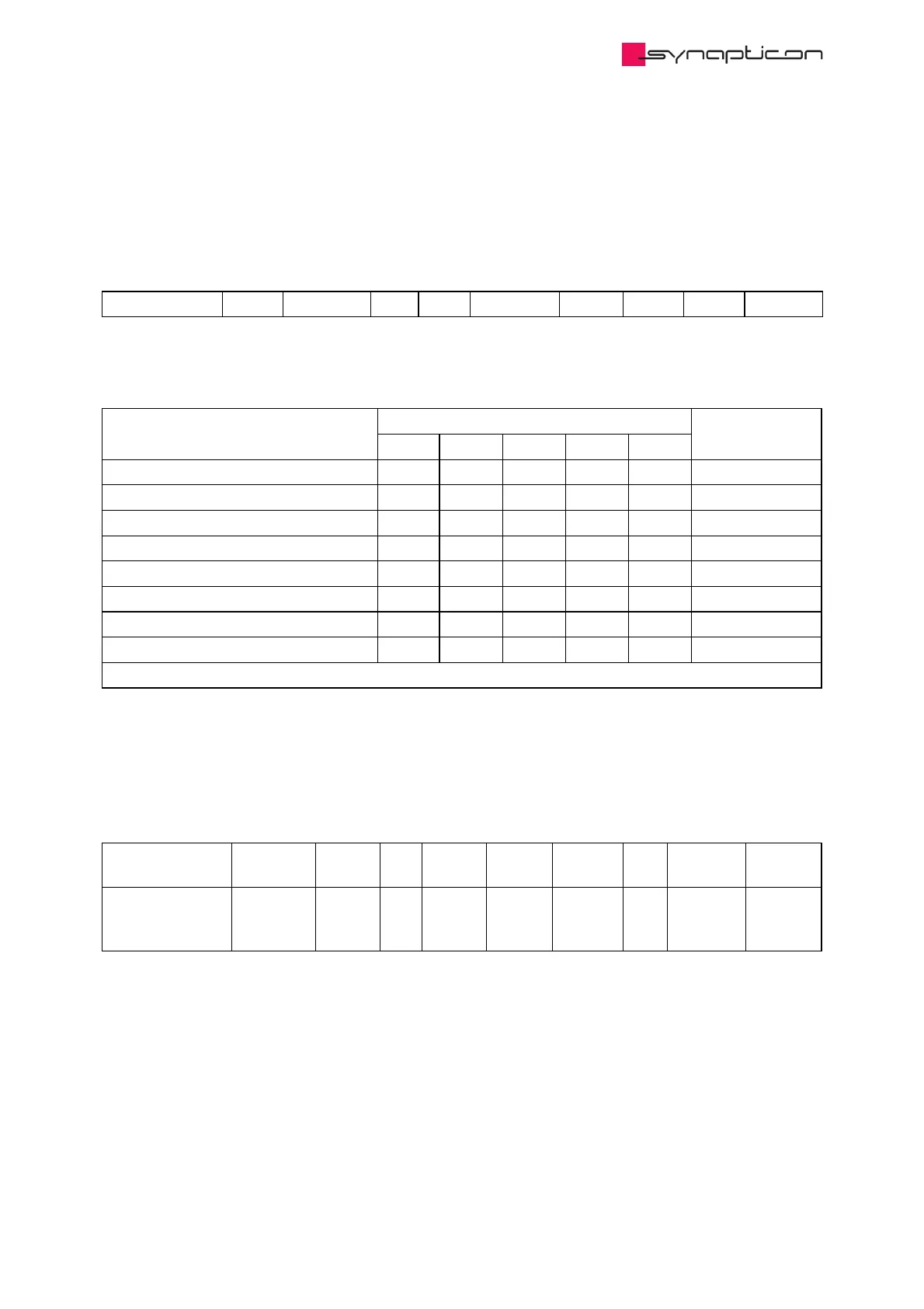
15 10 9 8 7 6 3 2 1 0
ms r oms h fr oms eo qs ev so
MSB
LEGEND: ms = manufacturer-specific; r = reserved; oms = operation mode specific; h = halt; fr = fault reset; eo = enable
operation; qs = quick stop; ev = enable voltage; so = switch on
Command Bits of the controlword Transitions
Bit 7 Bit 3 Bit 2 Bit 1 Bit 0
Shutdown 0 X 1 1 0 2, 6, 8
Switch on 0 0 1 1 1 3
Switch on + enable operation 0 1 1 1 1 3 + 4 (NOTE)
Disable voltage 0 X X 0 X 7, 9, 10, 12
Quick stop 0 X 0 1 X 7, 10, 11
Disable operation 0 0 1 1 1 5
Enable operation 0 1 1 1 1 4, 16
Fault reset X X X X 15
NOTE Automatic transition to Enable operation state after executing SWITCHED ON state functionality.
Bits 9, 6, 5, and 4 of the controlword are operation mode specific. The halt function (bit 8) behaviour is
operation mode specific. If the bit is 1, the commanded motion shall be interrupted, the PDS shall behave as
defined in the halt option code. After releasing the halt function, the commanded motion shall be continued if
possible.
The bit 10 is reserved for further use; it shall be set to 0. The bits 11, 12, 13, 14, and 15 are manufacturer-
specific.
Name Index:Sub Type Bit
Size
Min
Data
Max
Data
Default
Data
Unit Access PDO
Mapping
Controlword 0x6040:0 UINT 16 0 readwrite Receive
PDO
(Outputs)
 Loading...

