1.4.1.3 Installing the module and setting the threshold voltage
To install your module, mount it in an appropriate place with good cooling. Make sure the bottom is connected
to some metal structure thermally conductive.
Important
To ensure optimal performance, an appropriate heat conductivity is essential. It is recommended to use
silicon paste or a thermal pad.
Attention
Because the mounting holes are connected to the GND plane in the PCB, the isolation will break when a
conductive Spacer is used between the mounting holes on the PCB and chassis. This can violate an
existing earthing system and if a SELV power supply is used it may become PELV.
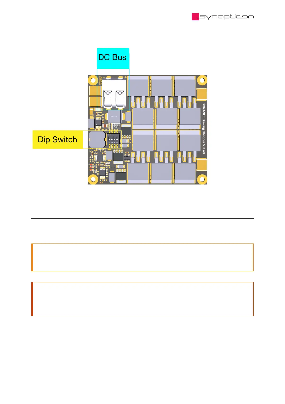
Connect the braking chopper wires to the DC bus. The chopper board must be installed in parallel to drive
boards. To set the threshold voltage please use the dip switches found on the top side of the board in five
levels: 50 V, 53 V, 54 V, 55 V or 57 V.
 Loading...

