3.1.8.2.1.2 Cyclic Synchronous Velocity Mode
The velocity control modes allow the EtherCAT master to send desired velocities to the SOMANET drive. The
drive will make sure these velocity values are reached by the motor (if the motor is physically able to do so).
In this mode, the trajectory generator is located in the control device, not in the servo drive. In a cyclic
synchronous manner, it provides a target velocity to the drive device, which performs velocity control and
torque control. If desired, the position control loop may be closed over the communication system. Optionally,
a velocity offset and a torque offset may be provided by the control system in order to allow a second source
for velocity and/or a torque feed forward.
Position sensors are supported and the velocity may be calculated by taking the derivative.
The cyclic synchronous velocity mode covers the following sub-functions:
demand value input;
velocity capture using position sensor;
velocity control function with appropriate input and output signals.
The behavior of the control function is influenced by control parameters such as limit functions, which are
externally applicable.
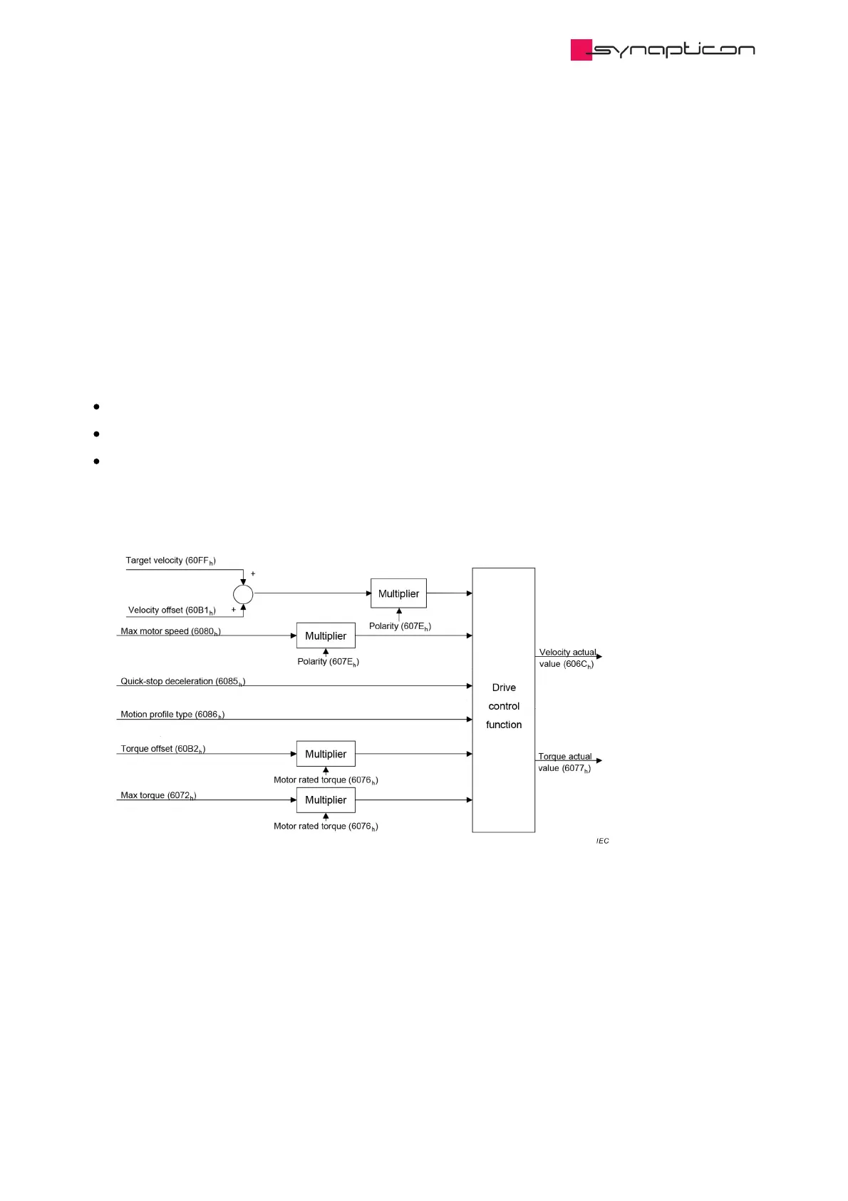
The figure above shows the inputs and outputs of the drive control function. The input (from the control
device point of view) are the target velocity and optionally, a velocity offset (to be added to the target velocity)
as well as a torque offset. The drive control function in the diagram contains both the velocity controller and
the torque controller, where the output of the velocity control loop is used as an input for the torque control
loop.
The drive device supports limitation of motor speed and a quick stop function for emergency reasons.
The time period between two updates of the target velocity and/or additive velocity can be interpolated for
smooth trajectories.
The velocity actual value is used as mandatory output to the control device. Another output is the torque
 Loading...

