EasyManuals Logo
Home>SYNAPTICON>Servo Drives>SOMANET Node Series

SYNAPTICON SOMANET Node Series User Manual

Default Icon
887 pages
To Next Page IconTo Next Page
To Previous Page IconTo Previous Page
Page #685 background imageLoading...
Page #685 background image
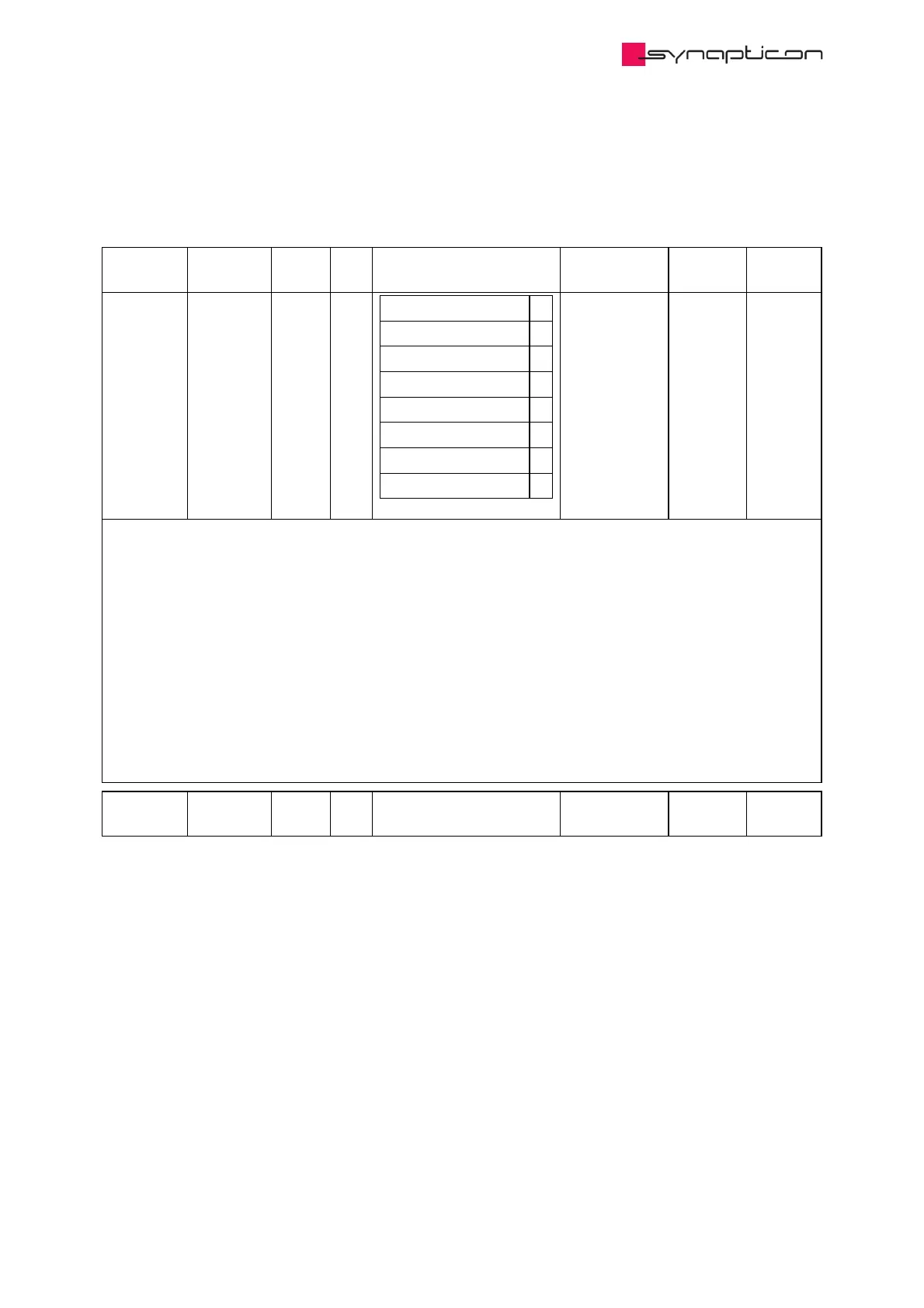
3.1.9.1.72 0x2202 BiSS encoder 2
Configuration parameters for second BISS encoder.
Name Index:Sub Type Bit
Size
Options Unit Access PDO
Mapping
Type 0x2202:1 USINT 8
HALL 1
Incremental 2
A-Format 3
BISS 4
REM 16MT 6
SSI 7
iC-MD 8
iC-NQC 9
readonly
(default)
The implementation of the BiSS service expects an encoder that has the following frame structure:
- SLO line high when ready.
- Ack bit (which can be extended to multiple bits by the encoder).
- Start bit when the encoder is ready to transmit the data.
- CDS bit for register communication.
- Payload (composed by Multiturn bits + Singleturn bits + Filling bits, in this order).
- Error and warning bits, in this order.
- 6-bit CRC.
- Timeout.
Name Index:Sub Type Bit
Size
Options Unit Access PDO
Mapping
Synapticon Documentation
© 2021 Synapticon GmbH | Daimlerstraße 26 | D-71101 Schönaich Documentation v 4.11.0 | Built 2021-07-23 685/887

Table of Contents

Other manuals for SYNAPTICON SOMANET Node Series

Questions and Answers:

Question and Answer IconNeed help?

Do you have a question about the SYNAPTICON SOMANET Node Series and is the answer not in the manual?

SYNAPTICON SOMANET Node Series Specifications

General IconGeneral
BrandSYNAPTICON
ModelSOMANET Node Series
CategoryServo Drives
LanguageEnglish

Related product manuals