EasyManuals Logo
Home>SYNAPTICON>Servo Drives>SOMANET Node Series

SYNAPTICON SOMANET Node Series User Manual

Default Icon
887 pages
To Next Page IconTo Next Page
To Previous Page IconTo Previous Page
Page #307 background imageLoading...
Page #307 background image
1.4.4.5 Strain relief
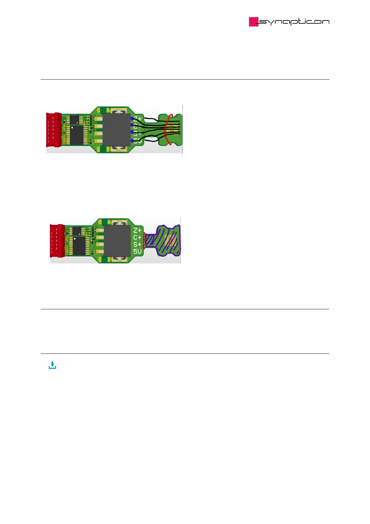
The board will be delivered with a strain relief. A cable tie can be used as a strain reliever:
On the right side of the image, the cable tie is symbolized in red and the cables in black. The Synapticon Logo
can be connected to PE, e.g. the shield of a cable. There is the possibility to place a CAP and a resistor between
PE and GND. In Standard version this is not placed.
If not needed, the strain reliever part can be broken off, then the module is shorter.
1.4.4.6 Soldered cables
Cables can also directly be soldered to the PCB. If this option is needed, please contact sales@synapticon.com
1.4.4.7 Downloads
DOWNLOAD 3D MODEL
Synapticon Documentation
© 2021 Synapticon GmbH | Daimlerstraße 26 | D-71101 Schönaich Documentation v 4.11.0 | Built 2021-07-23 307/887

Table of Contents

Other manuals for SYNAPTICON SOMANET Node Series

Questions and Answers:

Question and Answer IconNeed help?

Do you have a question about the SYNAPTICON SOMANET Node Series and is the answer not in the manual?

SYNAPTICON SOMANET Node Series Specifications

General IconGeneral
BrandSYNAPTICON
ModelSOMANET Node Series
CategoryServo Drives
LanguageEnglish

Related product manuals