EasyManuals Logo
Home>SYNAPTICON>Servo Drives>SOMANET Node Series

SYNAPTICON SOMANET Node Series User Manual

Default Icon
887 pages
To Next Page IconTo Next Page
To Previous Page IconTo Previous Page
Page #94 background imageLoading...
Page #94 background image
1.2.3.2.3.2 Planar displacements
Parameter Value
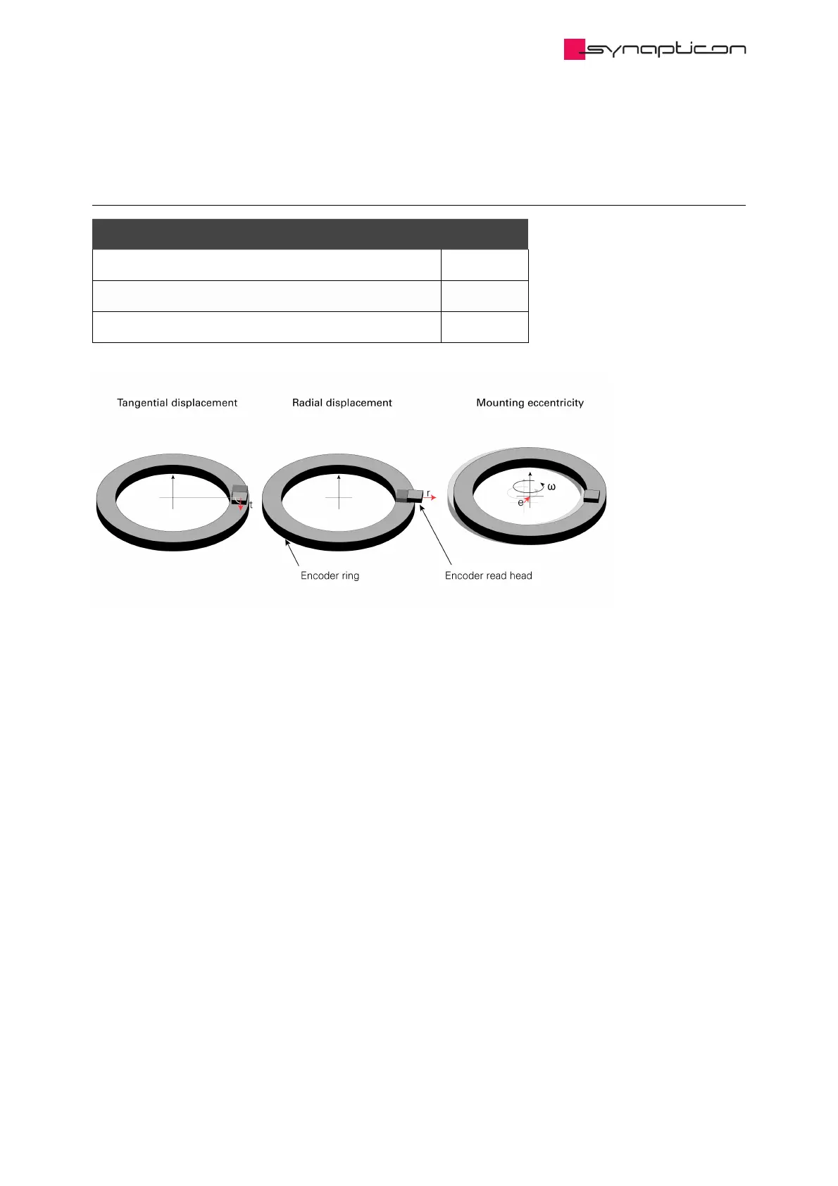
Radial displacement r max 0.3 mm
Tangential displacement t max 0.3 mm
Mounting eccentricity (radial runout) e max 0.1 mm
1.2.3.2.3.2.1 Radial displacement (r)
This basically means sliding the encoder chip off the scanning track. Deviations within the permissible range
increase the narrow angle error amplitude. This can be compensated by calibration. Moving the chip closer to
the center of the ring will have the most effect due to a direct influence on the main positioning (Master) track.
The other direction will mostly reduce the absolute position accuracy. If increased more than specified values,
the chip might fail sensing the magnetic field and throw an error.
Synapticon Documentation
© 2021 Synapticon GmbH | Daimlerstraße 26 | D-71101 Schönaich Documentation v 4.11.0 | Built 2021-07-23 94/887

Table of Contents

Other manuals for SYNAPTICON SOMANET Node Series

Questions and Answers:

Question and Answer IconNeed help?

Do you have a question about the SYNAPTICON SOMANET Node Series and is the answer not in the manual?

SYNAPTICON SOMANET Node Series Specifications

General IconGeneral
BrandSYNAPTICON
ModelSOMANET Node Series
CategoryServo Drives
LanguageEnglish

Related product manuals