Fig. 1: Normal motor phase configuration (sensor angle and rotor angle are both
increasing/decreasing simultaneously)
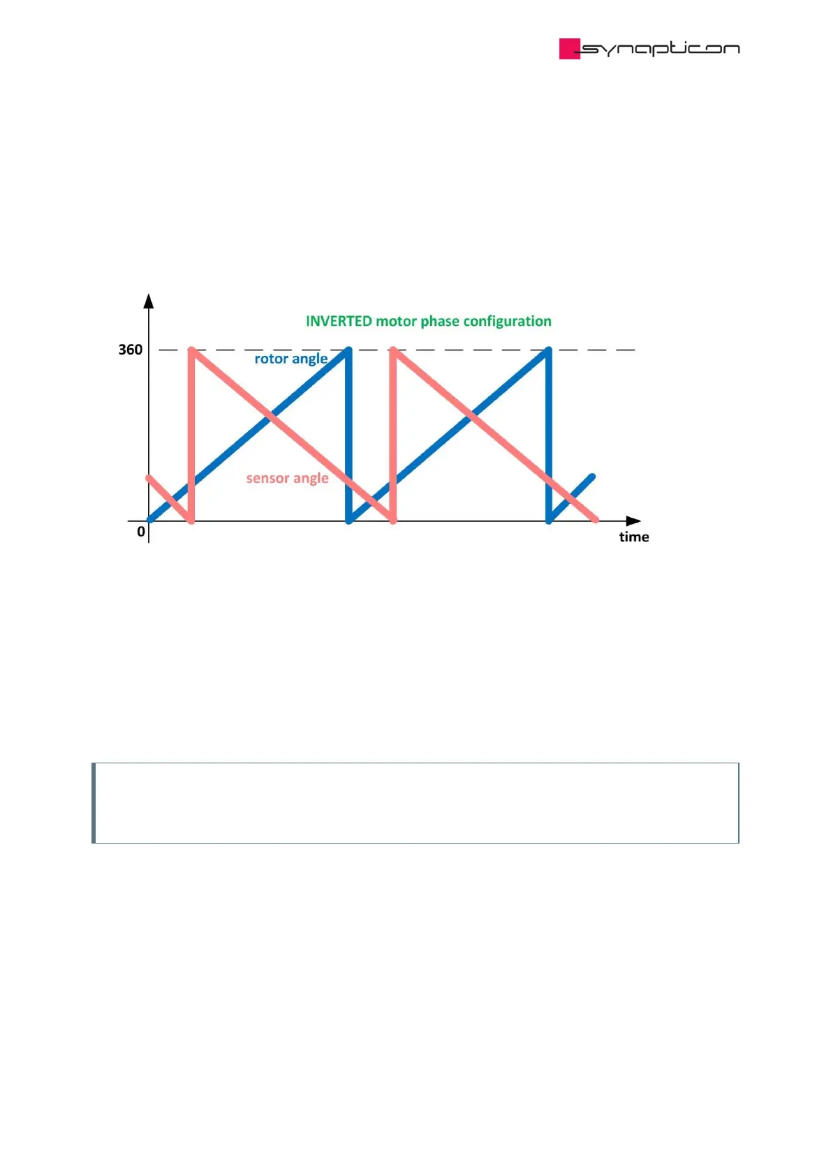
Fig. 2: Rotor angle and position sensor angle are not increasing/decreasing in the same
direction (Inverted motor phases)
However, sometimes the angle of position sensor is not increasing in the same direction of rotor angle. This
can happen if the position sensor is mechanically flipped, or if two of the stator phases are flipped. Figure 2
shows such a situation where the rotor angle and the position angle are not increasing/decreasing in the same
direction. This situation is called Inverted motor phase configuration.
2. The commutation angle offset (0x2001:1)
In most cases, the provided sensor angle contains a shift respect rotor angle. Figure 3 shows such a case
where the provided sensor angle has an offset respect rotor angle:
Offset Detection is carried out in the Diagnostics Opmode using OS-Commands.
Note
When quick stop is commanded during Offset detection, the procedure is aborted and the drive is
disabled.
 Loading...

