Note
Filtering comes at a cost of a phase shift. This might significantly limit the maximum sharpness of the
control loop.
3.1.8.3.9.5.1 A practical guide to low-pass filter design
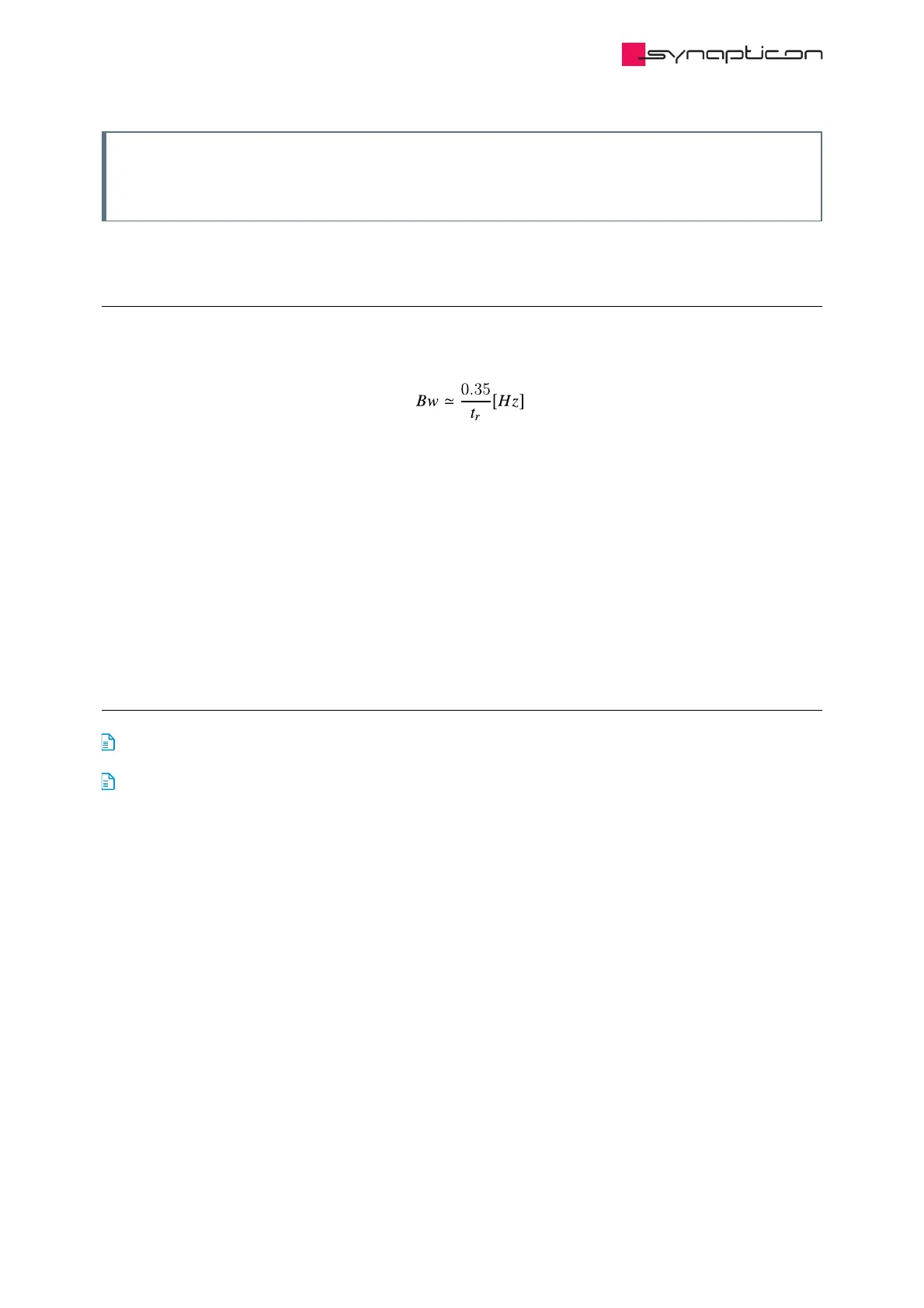
1. Determine the approximately required bandwidth of the control loop. This can be done based on the
reference profile specifications or roughly estimated from the actual rise time during a step response test:
2. Ideally, the filtered signal shouldn’t be modified until this frequency. The magnitude change and phase shift
caused by the filter have to be as little as possible. Thus, the filter cutoff frequency should be approximately
one decade higher (Bw ꞏ 10).
3. Examine the spectral density plot of the target signal and determine the frequency range that has to be
filtered out.
4. Enable a filter with the default cutoff frequency.
5. Try to change the cutoff frequency until an appropriate balance between noise filtering and phase-
shift/magnitude attenuation is reached.
3.1.8.3.9.5.2 Parameters related to feedback low-pass filters
0x2021 Velocity feedback filter Cut-off frequency of velocity feedback filter
0x2022 Position feedback filter Cut-off frequency of position feedback filter
 Loading...

