ProcedureforCounterbalancePressureTest(continued)
g287739
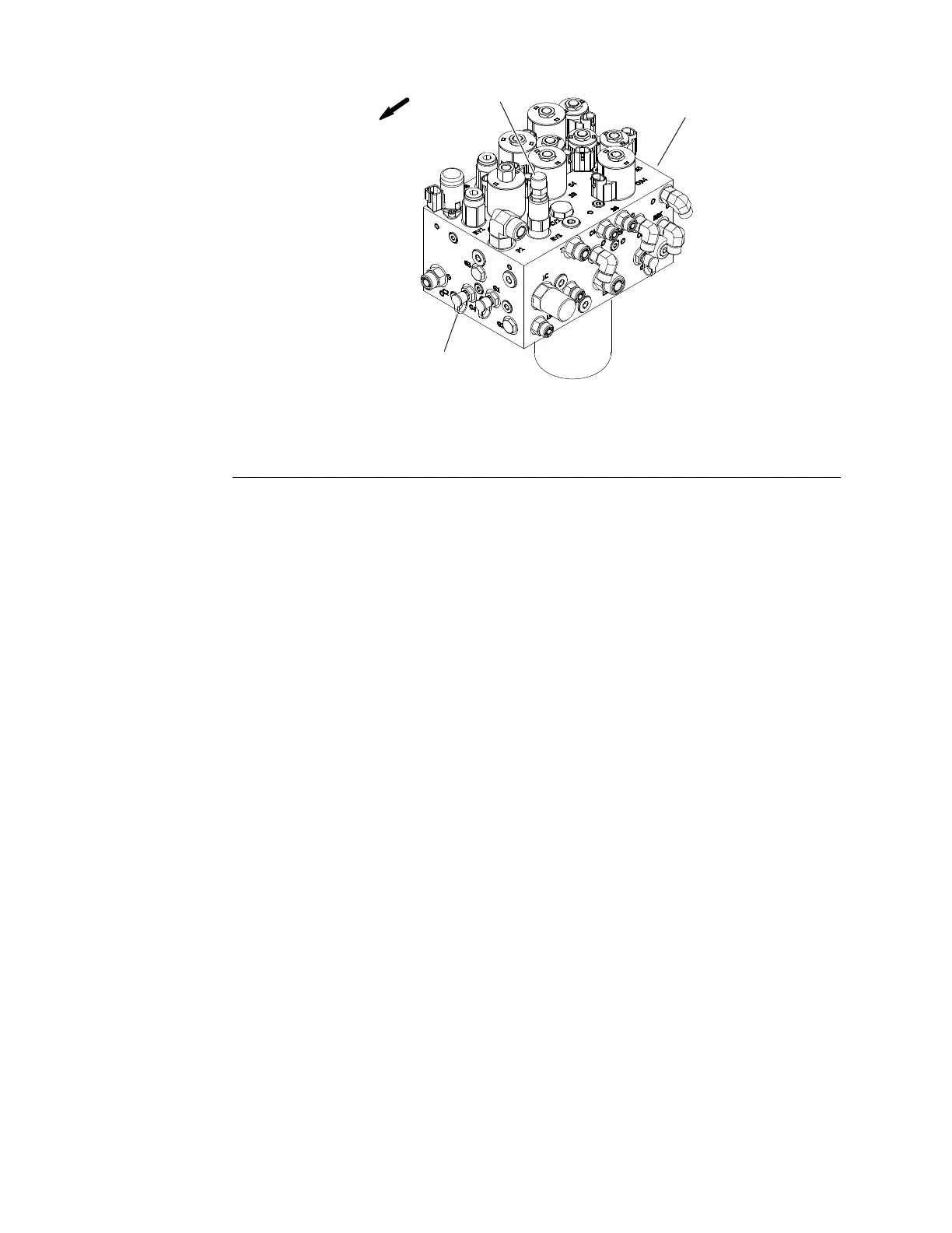
Figure54
1.Steering/liftmanifold3.Counterbalancevalve
2.T esttting(portG4)
4.Connecta70Bar(1000PSI)pressuregaugetotestttinginportG4on
steering/deckliftcontrolmanifold(Figure54).
5.Afterinstallingpressuregauge,startengineandrunatlowidlespeed.Check
forhydraulicleakageattesterconnectionsandcorrectbeforeproceeding
withtest.
6.Operatetheengineathighidlespeed(2530RPM)withnoloadonthe
system.Donotengagethecuttingdecks.
GAUGEREADINGTOBE:21to29bar(305to425PSI).
7.Stopengineandrecordtestresults.
Note:Ifhydraulicoilisnotatnormaloperatingtemperatureoriftraction
chargereliefpressureishigh,counterbalancepressurewillbehigherthan
normal.
8.Ifnecessary,adjustthecounterbalancevalve(RV3)sothatcounterbalance
pressureiscorrect(seeAdjustManifoldReliefValves(page5–72)).The
counterbalancevalve(RV3)islocatedonthetopofthesteering/decklift
manifold(Figure54).
9.Whencounterbalancetestingiscomplete,disconnectpressuregaugefrom
testtting.Lowerandsecurehood.
HydraulicSystem:Testing
Page5–46
Groundsmaster
®
5900&5910
16227SLRevB
 Loading...


