ProcedureforSteeringCircuitReliefPressureTest(continued)
g287791
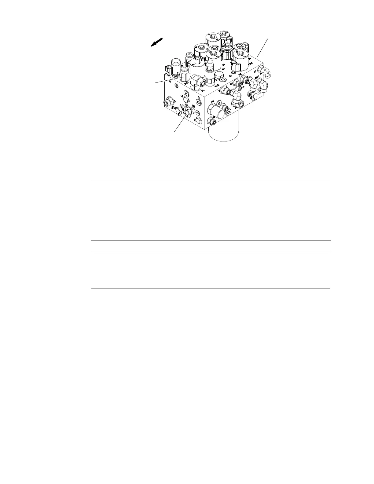
Figure69
1.Steering/liftmanifold3.ReliefvalveRV1
2.T esttting(portG1)
5.Connecta350Bar(5000PSI)pressuregaugewithhydraulichoseattached
totestttinginportG1onsteering/deckliftmanifold(Figure69).Route
gaugehosetoallowoperatortoviewthegauge.
6.Afterinstallingpressuregauge,startengineandrunatidlespeed.Checkfor
hydraulicleakageattestconnectionandcorrectbeforeproceedingwithtest.
7.Operatetheengineathighidlespeed(2530RPM).
IMPORTANT
Holdsteeringwheelatfulllockonlylongenoughtogetasystem
pressurereading.Holdingthesteeringwheelagainstthestopforan
extendedperiodmaydamagesteeringcomponents.
8.Turnsteeringwheelallthewayinonedirectionandmomentarilyholdthe
steeringwheelagainstresistance.
GAUGEREADINGTOBE:151to155bar(2200to2250PSI).
9.Releasesteeringwheel,stopengineandrecordtestresults.
Note:Ifsteeringreliefpressureisincorrectandlift/lowerproblemsalsoexist,
thenalgearpumpsectionshouldbesuspectedofwearandinefciency.
Ifsteeringwheelcontinuestoturnatendofcylindertravel(withlowerthan
normaleffort),thesteeringcylindersorsteeringcontrolvalveshouldbe
suspectedofwearordamage.
10.Ifreliefpressurespecicationisnotmet,adjustreliefvalve(RV1)in
steering/deckliftmanifold(Figure69)sothatreliefpressureiscorrect(see
AdjustManifoldReliefValves(page5–72)).
11.Whentestingiscomplete,disconnectpressuregaugefrommanifoldtest
tting.Lowerandsecurehood.
HydraulicSystem:Testing
Page5–64
Groundsmaster
®
5900&5910
16227SLRevB
 Loading...


