CuttingDeckControlManifoldInstallation(Figure110)(continued)
FRONT
1
2
3
4
34 N·m
(25 ft−lb)
34 N·m
(25 ft−lb)
102 N·m
(75 ft−lb)
102 N·m
(75 ft−lb)
102 N·m
(75 ft−lb)
4
6
5
g288134
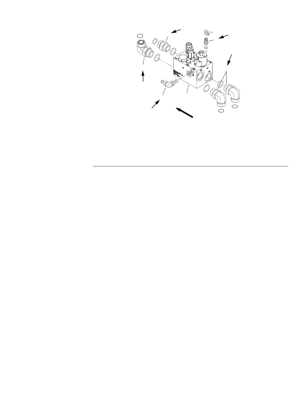
Figure113
LHDeckControlManifold
1.LHcontrolmanifold4.Hydraulic90ºtting(3)
2.Dustcap
5.Straighttting
3.Diagnostictting6.Hydraulic90ºtting
1.Ifttingswereremovedfrommanifold:
A.LubricatenewO−ringswithcleanhydraulicoil.InstalllubricatedO−rings
onttings.
B.Installttingsintomanifoldopeningsusingmarksmadeduringthe
removalprocesstoproperlyorientatettings.
C.Tightenhydraulicttingstotorquevalueprovided(Figure111,Figure112
andFigure113).Forinformationontighteningproceduresforhydraulic
ttings,seeInstallingtheHydraulicFittings(SAEStraightThreadO-Ring
Fittings)(page5–9).
2.PositionPTOcontrolmanifoldtotheframeandsecurewithtwo(2)cap
screws,atwashersandangenuts.
3.Removecapsandplugsfromttingsandhoses.Properlyconnecthydraulic
linestomanifold(seeInstallingHydraulicHosesandTubes(O-RingFace
Seal)(page5–7)).
4.Connectwireharnessconnectortotheproportionalreliefvalvesolenoid.
5.Makesurehydraulictankisfull.Addcorrectoilifnecessary.
6.Checkhydraulicsystemforleaksbeforereturningthemachinetoservice.
Groundsmaster
®
5900&5910
Page5–127
HydraulicSystem:ServiceandRepairs
16227SLRevB
 Loading...


