FRONT
FRONT
1
2 (T7)
3 (T6)
3 (T6)
3 (T6)
4 (T3)
4 (T3)
4 (T3)
4 (T3)
4 (T3)
4 (T3)
4 (T3)
5 (T4)
5 (T4)
5 (T4)
5 (T4)
6 (T7)
7 (T3)
8 (T3)
9
10 (T3)
11 (T4)
11 (T4)
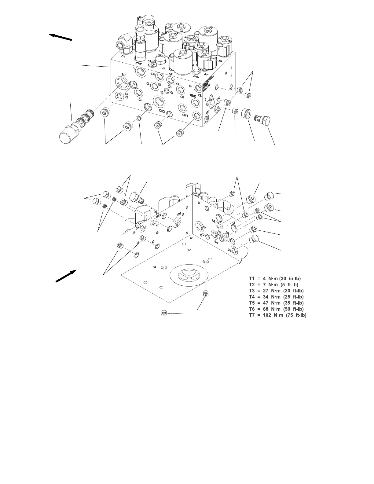
g288215
Figure133
1.Manifoldblock5.#6zeroleakplugwithO−ring(6)9.Orice−0.055inOR2andOR6
2.Pressurecompensator−LC6.#10zeroleakplugwithO−ring10.Checkvalve−CV3
3.#8zeroleakplugwithO−ring(4)
7.Checkvalve−CV2
11.#6zeroleakplugwithO−ring(2)
4.#4zeroleakplugwithO−ring(12)8.#4zeroleakplugwithO−ring(2)
Theportsontheliftcontrolmanifoldaremarkedforeasyidenticationof
components.Example:P1isthesupplyportfromthegearpumpandS1isthe
locationforsolenoidvalve#1(seeAHydraulicSchematic(pageA–3)toidentify
thefunctionofthehydrauliclinesandcartridgevalvesateachport).
Althoughnotrecommendedinmostsituations,reliefvalveRV1,RV2andRV3
areadjustable(seeAdjustManifoldReliefValves(page5–72)).
HydraulicSystem:ServiceandRepairs
Page5–156
Groundsmaster
®
5900&5910
16227SLRevB
 Loading...


