Removal(Figure292)(continued)
4.Useasuitablepullertoremovethesteeringtowertogetaccesstothe
fastenersthatsecurethesteeringtowertothemachine.
5.Slidetherubberbellowsupthesteeringtowertogetaccesstothefasteners
thatsecurethesteeringtowertothemachine.
6.Supportthesteeringcontrolvalvetopreventitfromfallingduringthesteering
towerremoval.
Note:Donotallowthesteeringcontrolvalvetohangfromthehydrauliclines.
7.RemovethesteeringtowerasneededusingtheFigure292asaguide.
g278374
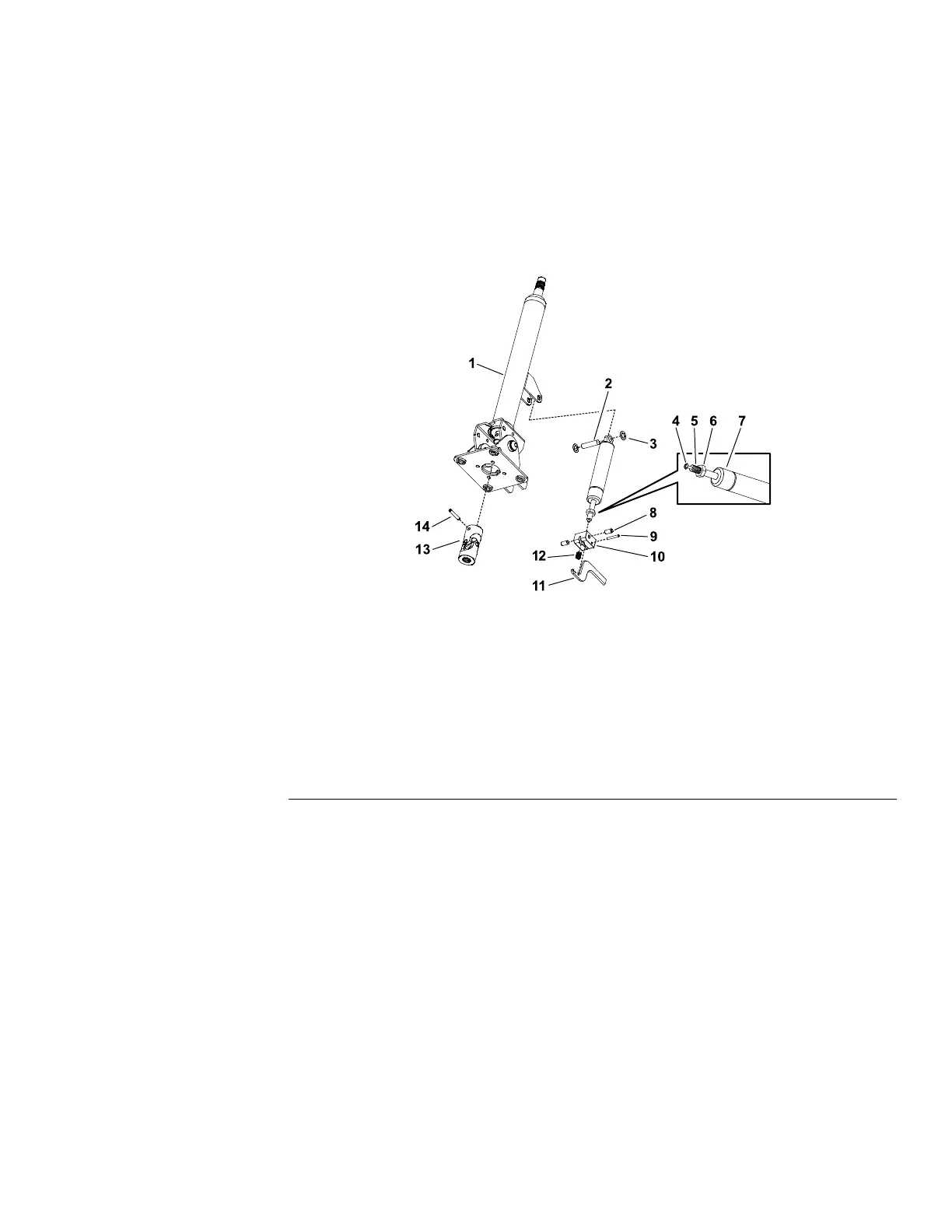
Figure293
1.Steeringtower8.Bolt(2each)
2.Pin9.Pin
3.Lockwasher(2each)
10.Pedalblock
4.Releasepin11.Pedal
5.Cylindershaft12.Spring
6.Jamnut13.Universaljoint
7.Cylinder
14.Pin
8.Disassemblethesteeringtowerassemblyasnecessary;refertoFigure293.
Installation(Figure292)
1.Assemblethesteeringtower;refertoFigure293.
2.Afterassembly,ensurethatthereleasepinontheendofthecylindershaftis
positionedagainstthepedal.Thejamnutonthecylindershaftcanbeused
toadjustthelocationofthereleasepin.
3.InstallthesteeringtowerusingtheFigure292asaguide.
4.Securethesteeringwheeltothesteeringcolumnassemblywiththeat
washerandlocknut.
5.Installthesteeringwheelcoverontothesteeringwheel.
Groundsmaster
®
5900&5910
Page7–9
Chassis:ServiceandRepairs
16227SLRevB
 Loading...


