g299725
Figure338
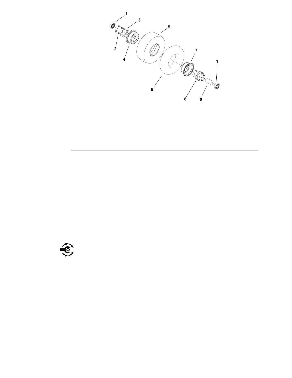
1.Bearing(2)
6.Innertube
2.Flangenut(4)7.Rimhalf
3.Plate8.Hub
4.Rimhalf
9.Bearingspacer
5.Tire
CastorWheelDisassembly(Figure337andFigure338)
Disassemblecastorforksandwheelsasneeded.
CastorWheelAssembly
1.Ifthecasterarmwasremovedformcuttingdeck,insertcastorarmboltswith
boltheadtowardtheoutsideofthecuttingdeck.
2.Assemblecastorforksandwheelsasneeded.
A.Makesuretoinstallallthecastorwheelsonallthecuttingdecksinthe
samemountingholeheightposition(lower,orupper).
B.Installcastorwheelssothatvalvestemextendstowardtheoutsideof
themachine.
C.Insertcastorwheelboltswithboltheadtowardtheoutsideofthemachine.
Tightencastorwheellocknutfrom81to108N·m(60to80ft−lb).
3.Castortirepressureshouldbe345kPa(50PSI).
4.Lubricatecastorforkgreasetting.
5.Checkheight−of−cutsettingandadjustifnecessary.
CuttingDecks:ServiceandRepairs
Page8–22
Groundsmaster
®
5900&5910
16227SLRevB
 Loading...


