7.5 Common Functions
7-59
7.5.4 Option Constants: F
J
Installing Option Cards
A maximum of three Option Cards can be installed in the Inverter. The installation location of each is deter-
mined by the type of Card. Be sure to install the Cards in their correct locations.
Table 7.7 Option Card Specifications
Type of card Model Specifications Location
AI-14U 14-bit analog, 2 inputs (voltage/current) C
Analog Reference Card
AI-14B 14-bits analog, 3 inputs C
DI-08 8-bit digital input (BCD/binary) C
Digital Reference Card
DI-16H2 16-bit digital input (BCD/binary) C
PG-A2 Open-collector/complementary, single input A
PG-B2 Complementary, A/B-phase input A
PG Speed Control Card
PG-D2 Line-driver, single input A
PG-X2 Line-driver, A/B-phase input A
AO-08 8-bit analog output, 2 channels D
Analog Monitor Card
AO-12 12-bit analog output, 2 channels D
Pulse Monitor Card
PO-36F Pulse frequency output D
Installation Procedure
1. Turn OFF the Inverter’s main-circuit power supply. Wait at least one minute (or at least three minutes
for models of 30 kW or more).
2. Remove the Inverter’s front cover. Check to be sure that the CHARGE LED is turned OFF.
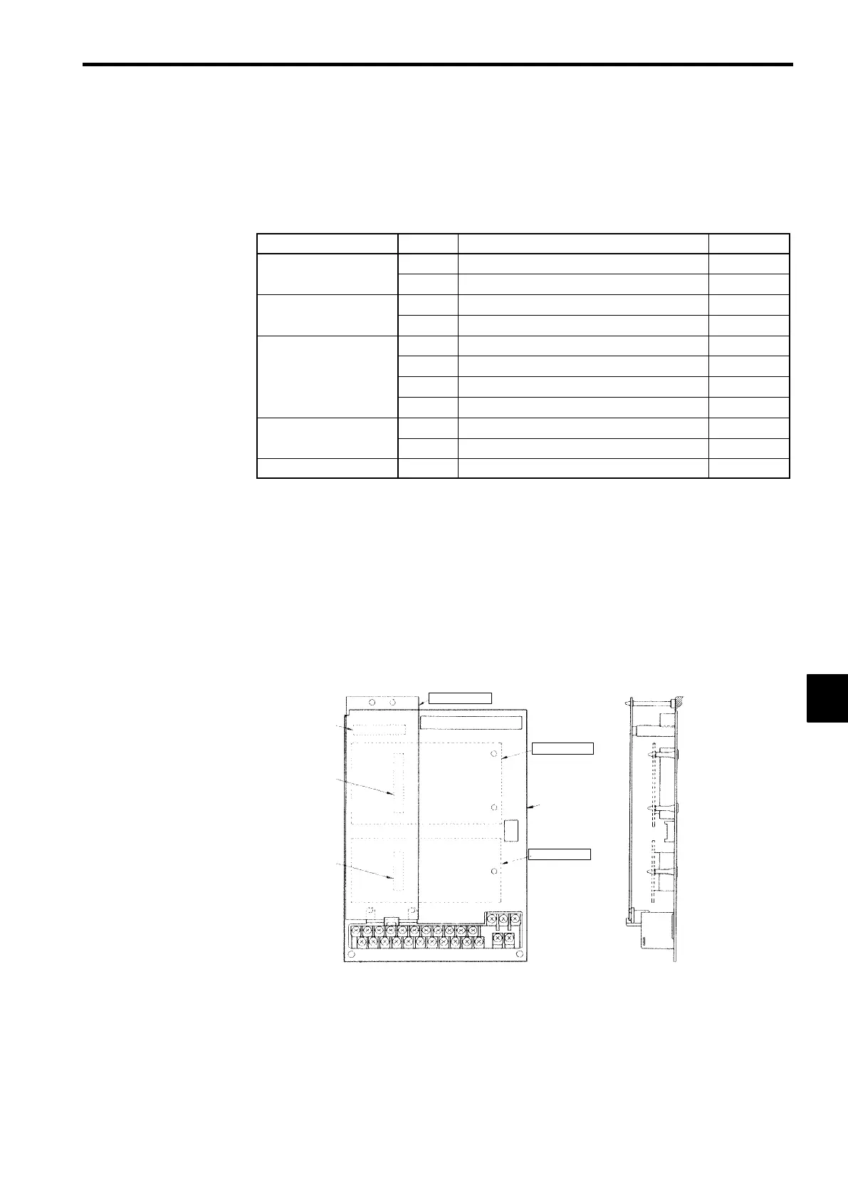
3. Check the Option Card’s installation location (A, C, or D). (See Figure 7.32.)
4. Insert the accessory spacer into the spacer mounting hole in the Inverter mounting base.
5. Align the Option Card connector with the connector position on the control board, and then pass the
spacer to the spacer mounting hole on the card.
Press firmly until the spacer snaps into place.
6. Connect the Option Card’s FG connection line to the Inverter ground terminal (terminal 12).
Option A
Option C
Control board
Option D
4CN
Option A con-
nector
2CN
Option C con-
nector
3CN
Option D con-
nector
[Front View]
Inverter
mounting base
[Side View]
7CN
Fig 7.32 Installation Locations for Option Cards
7
 Loading...