7.5.6 Protective Functions: L
7-94
J
Overtorque Detection Settings: L6-01 to L6-06
User
Change
Valid Access Levels
Constant
Number
Name
during
Opera-
tion
Setting
Range
Unit
Factory
Setting
V/f
Control
V/f with
PG
Open
Loop
Vector
Flux
Vector
L6-01
Torque detection
selection 1
×
0to4 − 0
B B B B
L6-02
Torque detection
level 1
×
0 to 300 % 150
B B B B
L6-03
Torque detection
time 1
×
0.0 to 10.0 s 0.1
B B B B
L6-04
Torque detection
selection 2
×
0to4 − 0
A A A A
L6-05
Torque detection
level 2
×
0 to 300 % 150
A A A A
L6-06
Torque detection
time 2
×
0.0 to 10.0 s 0.1
A A A A
D
The overtorque detection function detects an excessive mechanical load from an increase in the output
current (or output torque).
D
The settings in the torque detection selection constants (L6-01 and L6-04) determine whether overtor-
que conditions will be detected and what kind of processing will be performed if a overtorque condi-
tion is detected.
D
L6-01/L6-04 Settings
Setting Function Display
0
Overtorque detection disabled Overtorque detection 1 Overtorque output 2
1
Detect only during speed agree. Continue
operation even after detection. (Minor
fault)
“OL3” blinks “OL4” blinks
2
Detect overtorque at any time. Continue
operation even after detection. (Minor
fault)
“OL3” blinks “OL4” blinks
3
Detect only during speed agree. Stop out-
put after detection. (Fault
)
“OL3” lights “OL4” lights
4
Detect overtorque at any time. Stop output
after detection. (Fault)
“OL3” lights “OL4” lights
D
When overtorque detection is enabled, be sure to set the overtorque detection level (L6-02 or L6-05)
and the overtorque detection time (L6-02 or L6-05). An overtorque condition is detected when the cur-
rent exceeds the overtorque detection level for longer than the overtorque detection time.
D
The overtorque detection level settings depend on the control method:
•
Open-loop or flux vector control: Set as a percentage of the motor rated torque.
•
Normal V/f or V/f with PG feedback control: Set as a percentage of the Inverter rated current.
D
Any of the following functions can be set in a multi-function output (H2-01, H2-02, or H2-03) to indi-
cate fact that an overtorque condition has been detected.
S
Setting B: Overtorque detection 1 (NO)
S
Setting
18: Overtorque detection 2 (NO)
S Setting 17: Overtorque detection 1 (NC) S Setting 19: Overtorque detection 2 (NC)
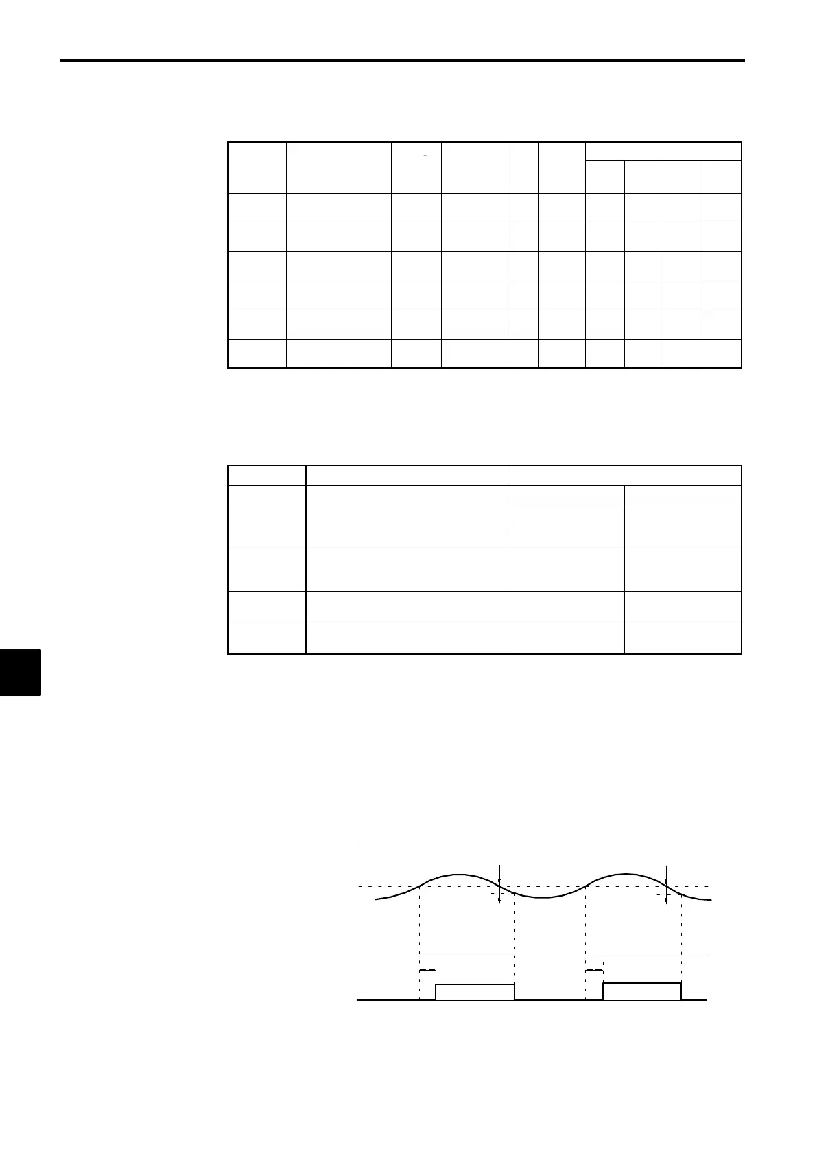
Motor current
(Output torque)
L6-02 or L6-05
Overtorque Detection 1 (N.O.)
or Overtorque Detection 2
(N.O.)
ON
L6-03
or
L6-06
::
ON
L6-03
or
L6-06
* The overtorque detection is cleared when the current drops about 5% of the
Inverter’s rated current (or the motor’s rated torque).
Fig 7.51 Timing Chart for Overtorque Detection
7
 Loading...