7.5.5 External Terminal Functions: H
7-70
•
The current motor selection can be monitored at a multi-function output terminal by setting “1C”
(motor selection monitor) for a constant from H2-01 to 03 (multi-function outputs).
•
Set the Basic (3) or Advanced (4) access level in the initialize setting A1-01 (access level).
•
The constants being used will changed as shown in the following table for the motor switch com-
mand.
Motor Switch command OPEN (motor 1) CLOSED (motor 2)
Control method *
A1-02 (control method in initialize
settings)
E3-01 (motor 2 control method)
V/f characteristics
E1-04 to 13 (V/f characteristics)
E4-01 to 07 (motor 2 V/f character-
istics)
Motor constants
E2-01 to 09 (motor constants)
E5-01 to 06 (motor 2 motor
constants)
Motor selection monitor
OPEN CLOSED
D
When A1-02
≠
E3-01, the constants under 8.2.9 are initialized each time the motor is switched.
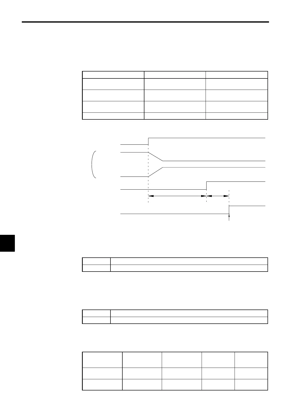
D
The timing chart for switching between motor 1 and motor 2 is shown below.
Turn ON the Forward (reverse) command only
after confirming the status of the motor selection
monitor.
Motor switching
contactor
(Setting: 1C)
Motor switch command
M1 operation
M2 operation
Motor selection monitor
Forward (reverse)
command
OFF
ON
Approx. 200 ms
Approx.
50 ms
OFF
ON
OFF
ON
OFF ON
OFF
ON
(Approx. 500 ms for control with a PG)
Fig
7.37
Timing Chart for Switching from Motor 1 to Motor 2
PID Control Disable (Setting: 19)
OFF
Enables PID control.
ON
Disables PID control. (Normal Inverter control)
D
With this setting, the multi-function input switches between PID control and normal Inverter control.
This function can be used to perform trial operation or jog operation with normal inverter control
(open-loop control) and then switch to PID control (closed-loop control using feedback) after adjust-
ing the system. The PID disable function can also be used to switch to open-loop control when there
is a problem with the feedback value.
Constants Write Enable (Setting: 1B)
OFF
Write-protects all constants except for frequency monitor.
ON
Allows constants specified in Initialize mode to be changed.
D
With this setting, the multi-function input can be used to write-protect the Operator constants. When
the input is OFF, the Operation mode frequency can be monitored and the frequency can be changed
but other changes are prohibited.
Trim Control Increase and Decrease (Settings: 1C and 1D)
Output frequency
Reference frequency
+ trim control level
(d4-02)
Reference frequency −
trim control level
(d4-02)
Reference fre-
quency
Reference fre-
quency
Trim Control In-
crease
ON OFF ON OFF
Trim Control De-
crease
OFF ON ON OFF
7
 Loading...