Advanced Operation
7.1.3 Setting/Adjusting Motor Constants
7-6
7.1.3 Setting/Adjusting Motor Constants
J
Adjusting the V/f Pattern: E1-04 through E1-10, E1-13
Normally it isn’t necessary to adjust the V/f pattern with open-loop vector control. Adjust the V/f pattern
when you want to change the maximum output frequency setting or decrease the Inverter’s output voltage
or when stalls are occurring during no-load operation.
To increase the motor’s rated speed, increase the maximum output frequency in E1-04 in programming
mode after autotuning.
It is possible to make user-defined V/f pattern settings (E1-04 through E1-10) in open-loop vector control
mode. (The preset V/f patterns cannot be selected.)
User
Change
Valid Access Levels
Constant
Number
Name
during
Opera-
tion
Setting
Range
Unit
Factory
Setting
V/f
Control
V/f with
PG
Open
Loop
Vector
Flux
Vector
E1-04
Max. output fre-
quency
×
40.0 to
400.0
Hz 60.0
Q Q Q Q
E1-05
Max. voltage
×
0.0 to 255.0
*1
VA C 200.0
*1
Q Q Q Q
E1-06
Base frequency
×
0.0 to 400.0 Hz 60.0
Q Q Q Q
E1-07
Mid. output fre-
quency
×
0.0 to 400.0 Hz 3.0
*2
Q Q A
×
E1-08
Mid. output fre-
quency voltage
×
0.0 to 255.0
*1
VA C
11.0
*1, *2
Q Q A
×
E1-09
Min. output fre-
quency
×
0.0 to 400.0 Hz 0.5
Q Q Q A
E1-10
Min. output fre-
quency voltage
×
0.0 to 255.0
*1
VA C
2.0
*1, *2
Q Q A
×
E1-13
Base voltage
×
0.0 to 255.0 VA C 0.0
A A Q Q
* 1. These voltages are for 200 V class Inverters; double the voltage for 400 V class Inverters.
* 2. The default setting depends on the Inverter’s capacity. The default settings shown in the table
are for 200 V class, 0.4 to 1.5 kW Inverters. (See page 8 - 47.)
Note 1.The default settings for E1-07 through E1-10 depend on the control method. The default
settings shown in the table are for open-loop vector control. (See page 8 - 45.)
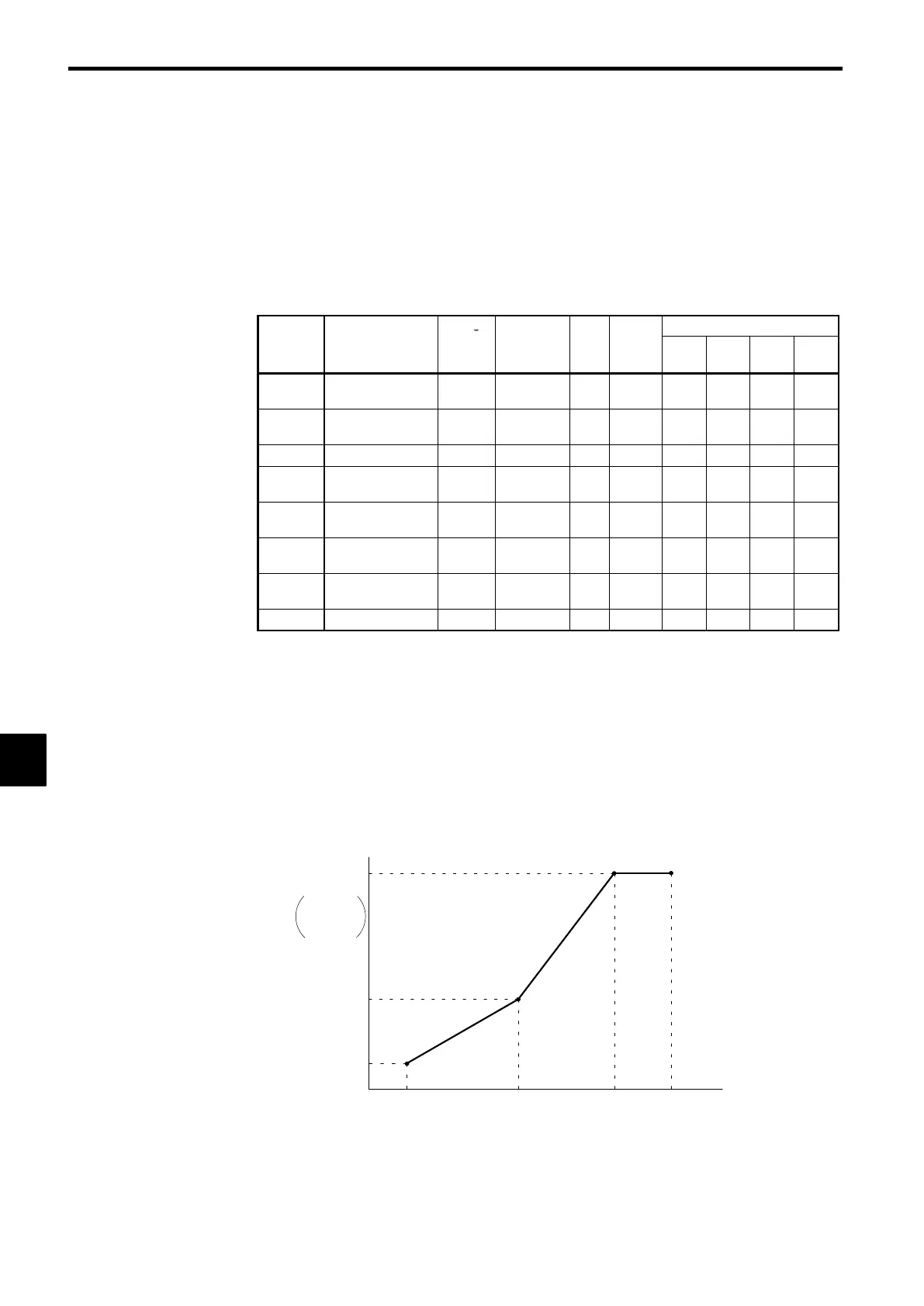
2. The four frequency settings must satisfy the following formula:
E1-04 (F
MAX
) ≥ E1-06 (F
A
) > E1-07 (F
B
) ≥ E1-09 (F
MIN
)
3. When making the V/f characteristics a straight line, set the same value in E1-07 (middle
output frequency) and E1-09 (minimum output frequency). In this case, constant E1-08
(middle output frequency voltage) will be disregarded.
4. If E1-13 is set to 0.0, the same value as in E1-13 will be set for E1-05. It does not normally
need to be set separately.
Frequency (Hz)
Output voltage (V)
VMAX
(E1-05)
VC
(E1-08)
VMIN
(E1-10)
FMIN
(E1-09)
FB
(E1-07)
FA
(E1-06)
FMAX
(E1-04)
VBASE
(E1-13)
Fig 7.3 User-defined V/f Pattern
7
 Loading...