User Constants
8.2.5 Options Constants: F
8-26
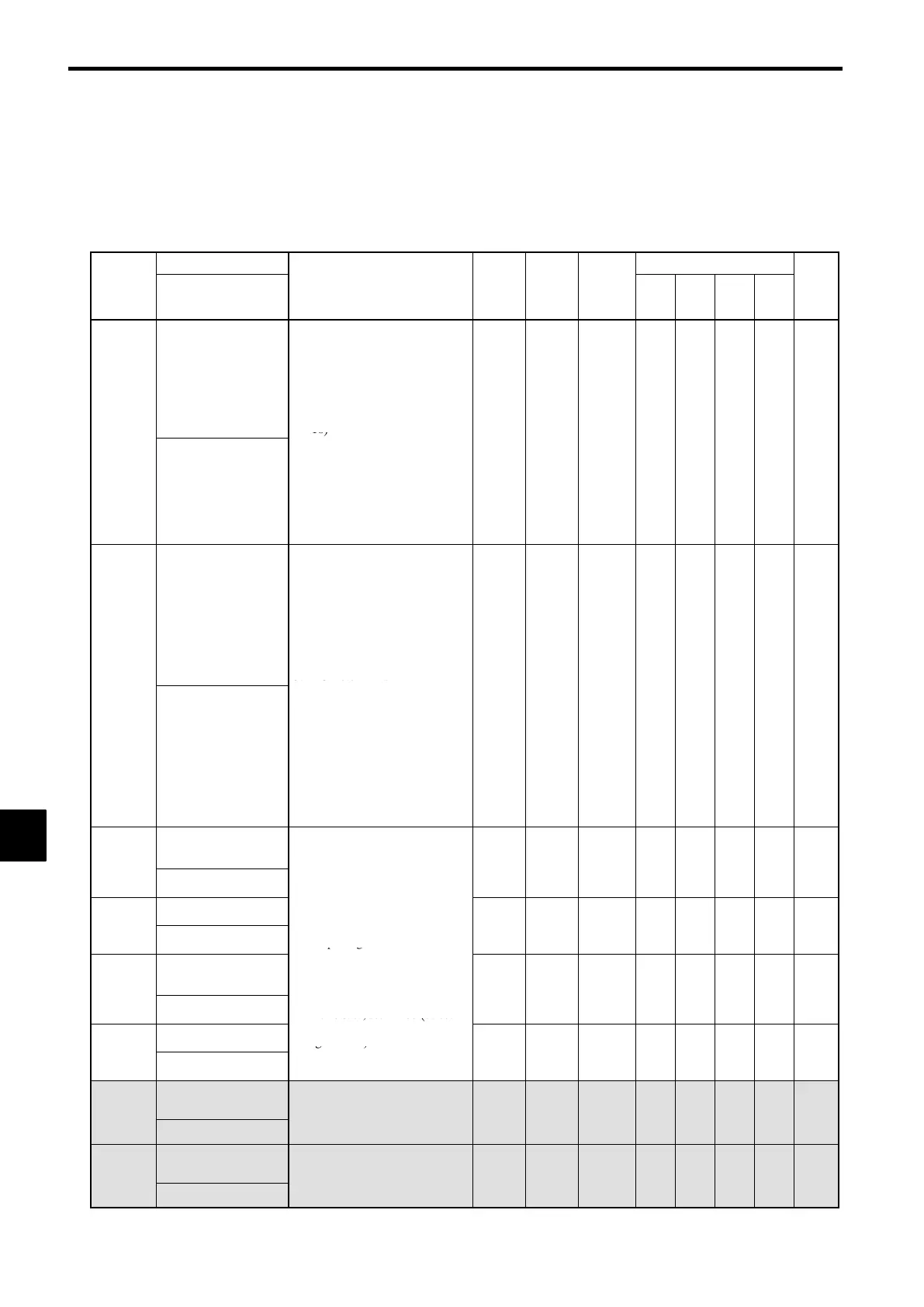
J Other Options Setup: F2 through F9
F2: Analog Reference Card F6: DO-08 Digital Output Card
F3: Digital Reference Card F7: Pulse Monitor Card
F4: Analog Monitor Card F8: SI-F/G
F5: DO-02 Digital Output Card F9: DOS/SI-B
Name
Change
Control Methods
Constant
Number
Display
Description
Setting
Range
Factory
Setting
during
Opera-
tion
V/f
V/f
with
PG
Open
Loop
Vector
Flux
Vector
Page
F2-01
Bi-polar or uni-polar
input selection
Sets the functions for channel 1 to
3 which are effective when the
AI-14B Analog Reference Card is
used.
0: 3-channel individual (Channel
1: terminal 13, Channel 2: ter-
minal 14, Channel 3: terminal
16)
0, 1 0
×
B B B B
7-60
AI-14 Input Sel
1: 3-channel addition (Addition
values are the frequency refer-
ence)
:When set to 0, select 1 for
b1-01. In this case the multi-
function input “Option/Inverter
selection” cannot be used.
,
Digital input option
Sets the Digital Reference Card
input method.
0: BCD 1% unit
1: BCD 0.1% unit
2: BCD 0.01% unit
3: BCD 1 Hz unit
4: BCD 0.1 Hz unit
5: BCD 0.01 Hz unit
F3-01
DI Input
6: BCD special setting (5-digit
input)
7: Binary input
:6 is only effective when the
DI-16H2 is used.
:When o1-03 is set to “2” or
higher, the input will be BCD,
and the units will change to the
o1-03 setting.
0to7 0
×
B B B B
7-60
F4-01
Channel 1 monitor
selection
Effective when the Analog Moni-
tor Card is used.
1to38 2
×
B B B B
7-61
AO Ch1 Select
Monitor selection:
Set the number of the monitor
Channel 1 gain
item to be output. (U1-
)
Gain:
0.00 to
F4-02
AO Ch1 Gain
Set the multiple of 10 V for
outputting monitor items.
.
2.50
1.00 f
B B B B
7-61
F4-03
Channel 2 monitor
selection
:4, 10, 11, 12, 13, 14, 25, 28 can-
not be set. 29 to 31 are not
used. When the AO-12 is used
1to38 3
×
B B B B
7-61
AO Ch2 Select
.
outputs of ± 10 V are possible.
In this case, set H4-07 (select
Channel 2 gain
multi-function analog output
signal level) to 1. When the
0.00 to
F4-04
AO Ch2 Gain
AO-08 is used, only outputs of
0 to +10 V are possible.
.
2.50
0.50
f
B B B B
7-61
F4-05
Channel 1 output
monitor bias
Sets the channel 1 item bias to
100%/10 V when the analog mon-
−10.0 to
0.0 f
B B B B
7-61
AO Ch1 Bias
itor card is used.
10.0
.
F4-06
Channel 2 output
monitor bias
Sets the channel 2 item bias to
100%/10 V when the analog mon-
−10.0 to
0.0 f
B B B B
7-61
AO Ch2 Bias
itor card is used.
10.0
.
8
 Loading...