Wiring
3.4.3 Main Circuit Configurations
3-10
3.4.3 Main Circuit Configurations
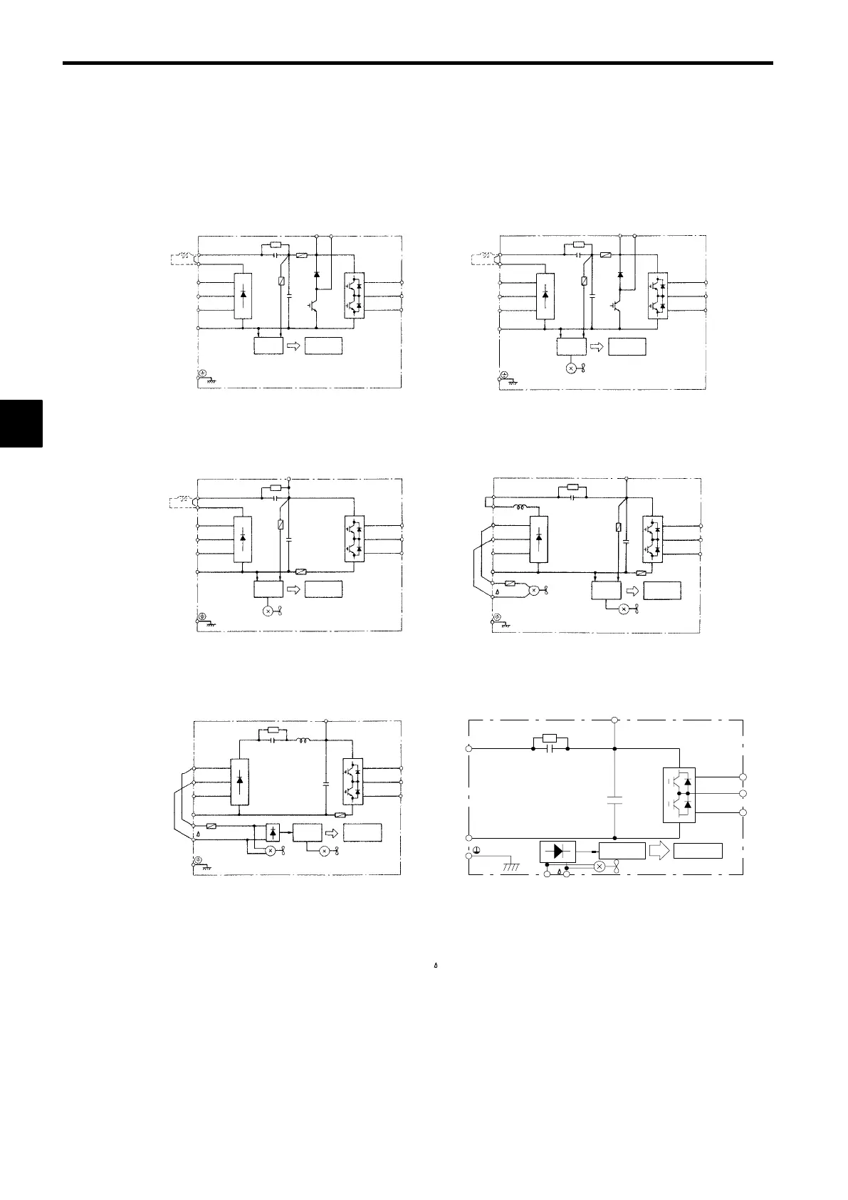
The main circuit configurations are shown in Figure 3.4 and Figure 3.5.
J
200 V Class
CIMR-G5A20P4 to 21P5 (0.4 to 1.5 kW)
CIMR-G5A2011 to 2015 (11, 15 kW)
CIMR-G5A2030 to 2075 (30 to 75 kW)
CIMR-G5A22P2 to 27P5 (2.2 to 7.5 kW)
CIMR-G5A2018 to 2022 (18.5, 22 kW)
(DCL
option)
V(T2)
W(T3)
Power
supply
(RCC)
U(T1)
+
B2B1
©
T(L3)
S(L2)
¨2
¨1
R(L1)
Control
circuits
V(T2)
W(T3)
Power
supply
(RCC)
U(T1)
+
B2B1
©
T(L3)
S(L2)
¨2
¨1
R(L1)
Control
circuits
(DCL
option)
Fin cooling fan
*2
*
2
*1
*1
V(T2)
W(T3)
Power
supply
(RCC)
U(T1)
+
©
T(L3)
S(L2)
¨2
¨1
R(L1)
Control
circuits
(DCL
option)
Fin cooling fan
V
W
Power
supply
(RCC)
U
+
©
T
S
¨2
¨1
R
Control
circuits
Fin cool-
ing fan
¨3
r
Internal
cooling fan
¨3
*1
*1
*
2
*3
V
W
Power
supply
(RCC)
U
+
©
T
S
R
Control
circuits
Fin cooling fan
r
Internal
cooling fan
¨3
*
1
* 1 Prewired at the factory.
* 2 Remove the short-circuit bar from between ¨1 and ¨2 when connecting a DC
reactor to Inverters of 15 kW or less.
* 3 Prewired at the factory. When supplying power to the main circuits from the DC
power supply, remove the wiring from R-r and S- .
CIMR-G5AD030 to D075 (30 to 75 kW)
©
¨1
¨3
+
Power sup-
ply (RCC)
Control
circuits
Fin cooling fan
r
V
W
U
Fig 3.4 200 V Class Inverter Main Circuit Configurations
3
 Loading...