7.5 Common Functions
7-57
7.5.3 Reference Constants: d
J
Frequency Reference Function: d2-01, d2-02
D
The frequency reference function sets the output frequency upper and lower limits.
D
When the frequency reference is zero and a run command is input, the motor operates at the frequency
reference lower limit (d2-02). The motor will not operate, however, if the lower limit is set lower than
the minimum output frequency (E1-09).
User
Change
Valid Access Levels
Constant
Number
Name
during
Opera-
tion
Setting
Range
Unit
Factory
Setting
V/f
Control
V/f with
PG
Open
Loop
Vector
Flux
Vector
d2-01
Frequency reference
upper limit
×
0.0 to 110.0
%
100.0
B B B B
d2-02
Frequency reference
lower limit
×
0.0 to 109.0 % 0.0
B B B B
D
The frequency reference upper and lower limits are set as a percentage of the maximum output fre-
quency (E1-04), in increments of 1%.
D
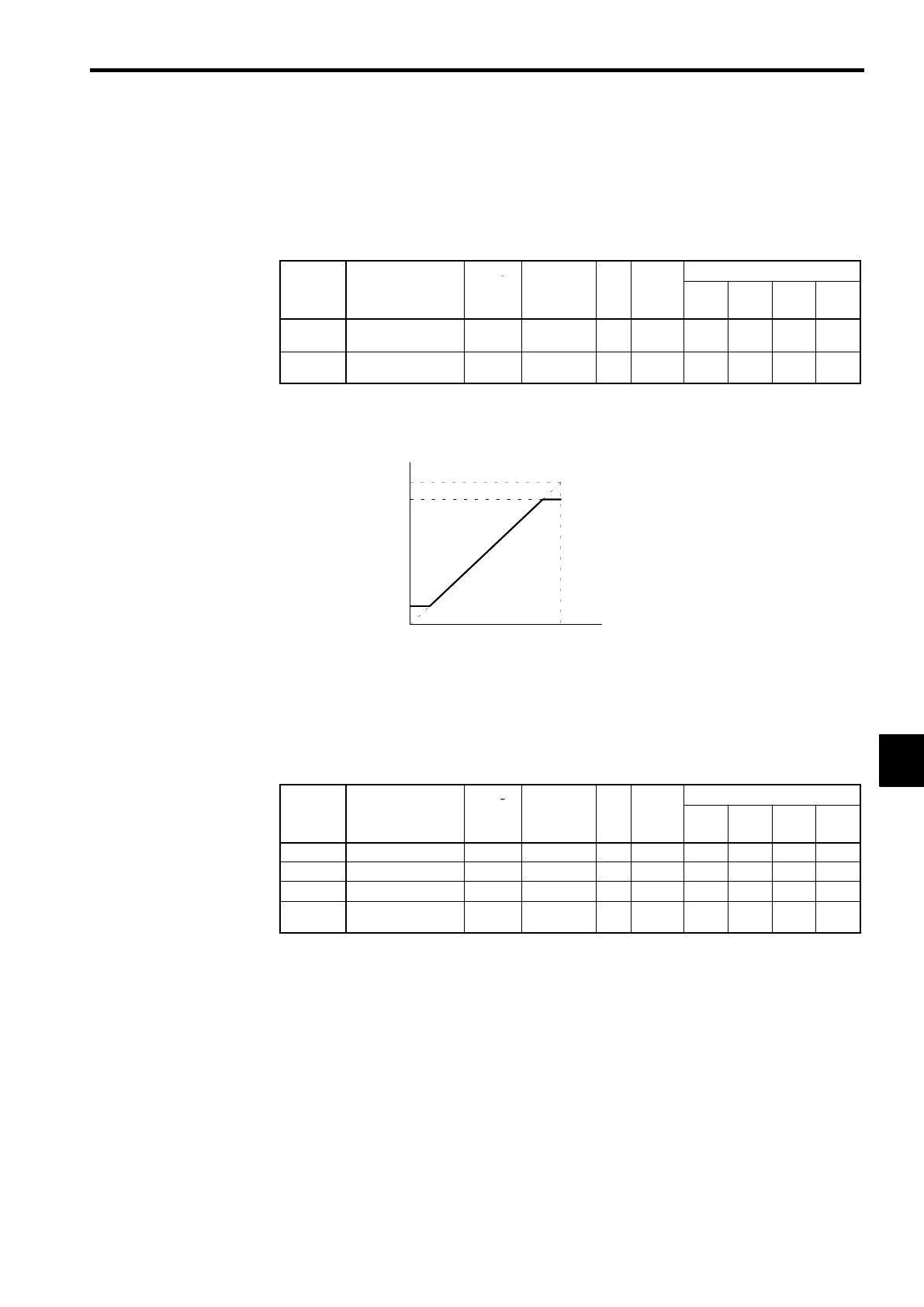
The upper and lower limits of the frequency reference are shown in Figure 7.30.
Set frequency reference
Internal frequency reference
Frequency reference
upper limit (d2-01)
Frequency reference
lower limit (d2-02)
Fig 7.30 Upper and Lower Limits of the Frequency Reference
J
Prohibited Frequency (Jump Frequency): d3-01 to d3-04
D
This function allows the prohibition or “jumping” of certain frequencies within the Inverter’s output
frequency range so that the motor can operate without resonant oscillations caused by some machine
systems.
D
It is also used for deadband control. The constants of the attached card can be accessed for reference
or to make settings by using the Basic access level (B).
User
Change
Valid Access Levels
Constant
Number
Name
during
Opera-
tion
Setting
Range
Unit
Factory
Setting
V/f
Control
V/f with
PG
Open
Loop
Vector
Flux
Vector
d3-01
Jump frequency 1
×
0.0 to 400.0 Hz 0.0
B B B B
d3-02
Jump frequency 2
×
0.0 to 400.0 Hz 0.0
B B B B
d3-03
Jump frequency 3
×
0.0 to 400.0 Hz 0.0
B B B B
d3-04
Jump frequency
width
×
0.0 to 20.0 Hz 1.0
B B B B
D
To disable this function, set the jump frequency references (d3-01 to d3-03) to 0.0 Hz.
D
For d3-01 to d3-03, set the center values of the frequencies to be jumped. Be sure to set the jump fre-
quency so that d3-03
≤
d3-02
≤
d3-01.
D
For d3-04, set the jump frequency bandwidth. The jump frequency
±
the jump frequency bandwidth
becomes the jump frequency range.
D
Operation is prohibited within the jump frequency range, but changes during acceleration and decel-
eration are smooth with no jumps.
D
The relation between the internal frequency reference and the set frequency references is shown in Fig-
ure 7.31.
7
 Loading...