User Constants
8.2.4 Motor Constant Constants: E
8-20
8.2.4 Motor Constant Constants: E
J
V/f Pattern: E1
Con-
Name
Change
Control Methods
stant
Num-
ber
Display
Description
Setting
Range
Factory
Setting
during
Opera-
tion
V/f
V/f
with
PG
Open
Loop
Vector
Flux
Vector
Page
E1-01
Input voltage
setting
Sets the Inverter input voltage in units of 1
V.
This settin
is used as the reference value
155 to
255
200
*
×
Q Q Q Q
6-18
6-21
Input Voltage
for functions such as the protection func-
tions.
*1
*1
6-33
6-40
Motor selection
0: Standard fan-cooled motor (general-pur-
pose motor)
1: Standard blower-cooled motor (Inverter-
-
E1-02
Motor Selec-
tion
exc
us
ve motor
2: Special motor (vector-exclusive motor)
:This setting is used as the reference value
for functions such as the protection func-
tions.
0to2 0
×
Q Q Q Q
-
6-40
E1-03
V/f pattern
selection
0 to E: Select from the 15 preset patterns.
-
0toF F
×
Q Q
× ×
6-22
V/F Selection
-
settings E1-04 to E1-10.)
Max. output
frequency
40.0 to
E1-04
Max Frequen-
cy
.
400.0
60.0
×
Q Q Q Q
6-26
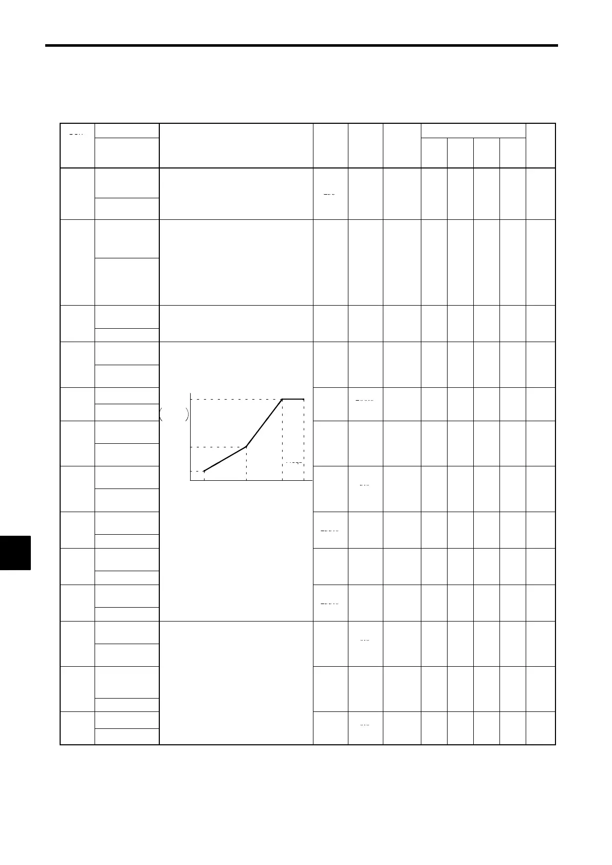
Max. voltage
Output voltage (V)
VMAX
0.0 to
200.0
E1-05
Max Voltage
(E1-05)
V BASE
-
.
*1
*1
×
Q Q Q Q
6-26
Base frequen-
cy
-
0.0 to
E1-06
Base Frequen-
cy
VC
(E1-08)
Frequ-
.
400.0
60.0
×
Q Q Q Q
6-26
Mid. output fre-
quency
VMIN
(E1-10)
ency
(Hz)
0.0 to
3.0
E1-07
Mid Frequency
A
(E1-09)
(E1-07)
(E1-06)
(E1-04)
.
400.0
*2
×
Q Q A
×
6-26
E1-08
Mid. output fre-
quency voltage
:To set V/f characteristics in a straight line,
set the same values for E1-07 and E1-09.
In this case, the settin
for E1-08 will be
0.0 to
255.0
11.0
*1
×
Q Q A
×
6-26
Mid Voltage A
,
disregarded.
*1
*2
E1-09
Min. output fre-
quency
Always ensure that the four frequencies
are set in the following manner:
E1-04
FMAX
≥ E1-06
FA
> E1-07
0.0 to
0.5
*
×
Q Q Q A
6-26
Min Frequency
(FB) ≥ E1-09 (FMIN)
400.0
*2
E1-10
Min. output fre-
quency voltage
0.0 to
255.0
2.0
*1
×
Q Q A
×
6-26
Min Voltage
*1
*2
Mid. output fre-
quency 2
0.0 to
0.0
E1-11
Mid Frequency
B
.
400.0
*3
×
A A A A
−−
E1-12
Mid. output fre-
quency voltage
2
Set only to fine-adjust V/f for the output
range when using flux vector control.
Normall
, this settin
is not re
uired.
0.0 to
255.0
*
0.0
*3
×
A A A A
−−
Mid Voltage B
,
.
*1
Base voltage
0.0 to
0.0
E1-13
Base Voltage
.
*1
*4
×
A A Q Q
6-26
* 1. These are values for a 200 V class Inverter. Values for the 400 V class Inverter are double.
* 2. When the control method is changed, the Inverter reverts to factory settings. (The open loop vector control factory settings will
be displayed.)
* 3. E1-11 and E1-12 are disregarded when set to 0.0.
* 4. E1-13 is set to the same value as E1-05 by autotuning.
8
 Loading...