6.1 Common Settings
6-13
Lengthen the minimum baseblock time (L2-03) when an overcurrent (OC) occurs during stopping. When the
power to an induction motor is turned OFF, the counter-electromotive force generated by the residual magnet-
ic field in the motor can cause an overcurrent to be detected when DC injection braking is applied.
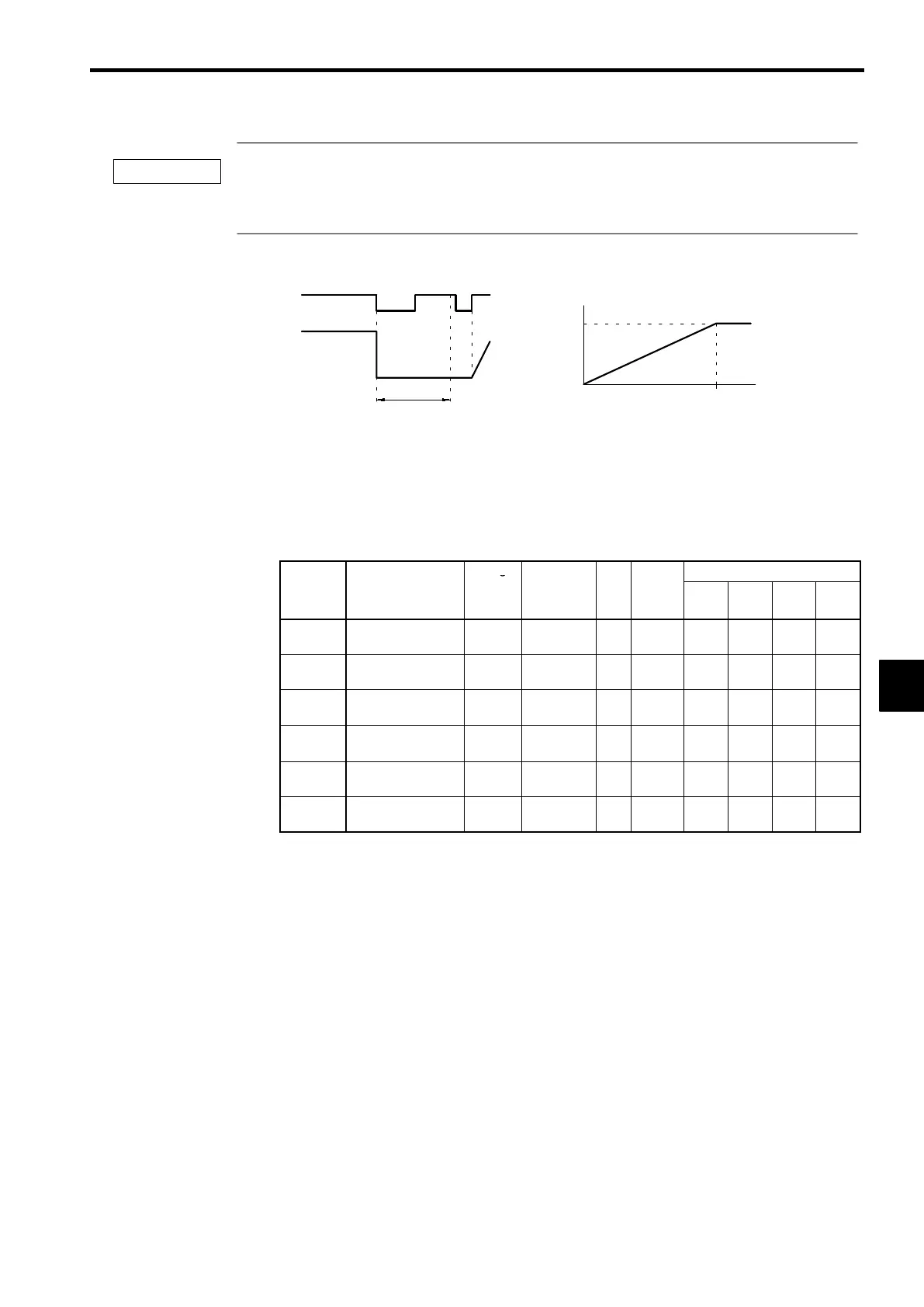
• Coast to Stop with Timer (b1-03 = 3)
Time T
0
Deceleration
time
Output frequency
when the stop
command is input
100% (Max. frequency)
Run command
ON OFF
Output frequency
ON ON
T
0
After the stop command is input, run commands are disregarded until the time T
0
has
elapsed. The time T
0
depends upon the output frequency when the stop command is
input and the deceleration time.
Fig 6.7 Coast to Stop with Timer
6.1.8 Multi-function Input Settings: H1-01 through H1-06
D
Set the functions for terminals 3 to 8. Set the functions of the multi-function inputs according to the
application.
User
Change
Valid Access Levels
Constant
Number
Name
during
Opera-
tion
Setting
Range
Unit
Factory
Setting
V/f
Control
V/f with
PG
Open
Loop
Vector
Flux
Vector
H1-01
Multi-function input
1 (terminal 3)
×
0to77 − 24
B B B B
H1-02
Multi-function input
2 (terminal 4)
×
0to77 − 14
B B B B
H1-03
Multi-function input
3 (terminal 5)
×
0to77 − 3 (0)
B B B B
H1-04
Multi-function input
4 (terminal 6)
×
0to77 − 4 (3)
B B B B
H1-05
Multi-function input
5 (terminal 7)
×
0to77 − 6 (4)
B B B B
H1-06
Multi-function input
6 (terminal 8)
×
0to77 − 8 (6)
B B B B
D
The default settings in parentheses are the default values when the Unit is initialized for 3-wire se-
quence control.
D
The constant settings that are used most often are explained below. Refer to chapter 7 Advanced Opera-
tion or the constant tables for details on the other settings.
S
3-wire sequence (forward/reverse run command):
Set “0”
S
Multi-step sped references 1 to 3 and jog command:
Set “3” to “6”
S
Acceleration/Deceleration Time Selectors 1 and 2:
Set “7” and “1A”
S
Emergency Stop:
Set “15”
S
FORWARD and REVERSE JOG References:
Set “12” and “13”
S
Terminal 13/14 Switch:
Set “1F”
6
IMPORTANT
 Loading...