7.3 Flux Vector Control
7-27
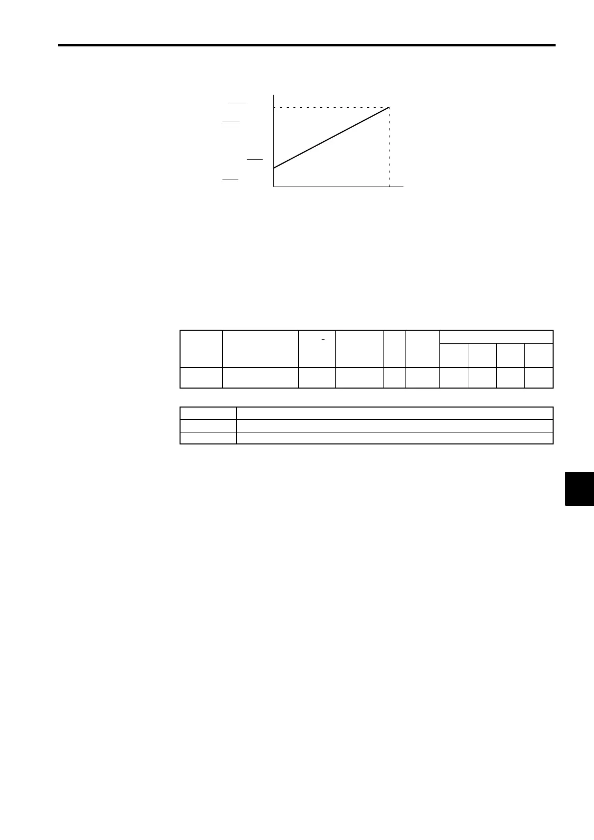
Input voltage
(Input current)
0V
(4 mA)
10 V
(20 mA)
Use the current values shown in pa-
rentheses when current input has
been selected.
Max. frequency ×
Gain
100
Max. output frequency ×
Bias
100
Rated torque ×
Gain
100
Rated torque ×
Bias
100
Reference value
Fig 7.13 Analog Input Gain and Bias Settings
7.3.4 Speed/Torque Control Switching Function
It is possible to switch between speed control and torque control when one of the multi-function inputs
(H1-01 to H1-06) is set to 71 (Speed/Torque Control Change). Speed control is performed when the input
is OFF and torque control is performed when the input is ON.
J
Torque Control Function Settings: d5-01
User
Change
Valid Access Levels
Constant
Number
Name
during
Opera-
tion
Setting
Range
Unit
Factory
Setting
V/f
Control
V/f with
PG
Open
Loop
Vector
Flux
Vector
d5-01
Torque control selec-
tion
×
0, 1 − 0
× × ×
A
D
Settings
Setting Function
0
Speed control (controlled by C5-01 to C5-07)
1
Torque control
D
Set constant d5-01 to 0 (speed control) when using the speed/torque control switching function.
7
 Loading...